HP Pavilion 15-ab500 Maintenance and Service Guide - Page 72
Power connector cable, Display cable
 |
View all HP Pavilion 15-ab500 manuals
Add to My Manuals
Save this manual to your list of manuals |
Page 72 highlights
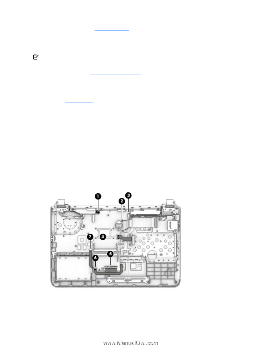
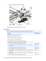
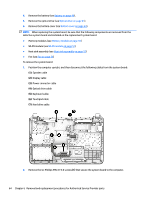
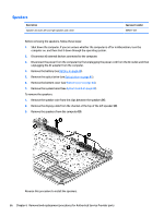
4. Remove the battery (see Battery on page 40). 5. Remove the optical drive (see Optical drive on page 41). 6. Remove the bottom cover (see Bottom cover on page 44). NOTE: When replacing the system board, be sure that the following components are removed from the defective system board and installed on the replacement system board: ● Memory modules (see Memory module on page 55) ● WLAN module (see WLAN module on page 51) ● Heat sink assembly (see Heat sink assembly on page 57) ● Fan (see Fan on page 56) To remove the system board: 1. Position the computer upright, and then disconnect the following cables from the system board: (1): Speaker cable (2): Display cable (3): Power connector cable (4): Optical drive cable (5): Keyboard cable (6): Touchpad cable (7): Hard drive cable 2. Remove the six Phillips PM2.0×3.0 screws (1) that secure the system board to the computer. 64 Chapter 6 Removal and replacement procedures for Authorized Service Provider parts
-
 1
1 -
2
-
3
-
4
-
5
-
6
-
7
-
8
-
9
-
10
-
11
-
12
-
13
-
14
-
15
-
16
-
17
-
18
-
19
-
20
-
21
-
22
-
23
-
24
-
25
-
26
-
27
-
28
-
29
-
30
-
31
-
32
-
33
-
34
-
35
-
36
-
37
-
38
-
39
-
40
-
41
-
42
-
43
-
44
-
45
-
46
-
47
-
48
-
49
-
50
-
51
-
52
-
53
-
54
-
55
-
56
-
57
-
58
-
59
-
60
-
61
-
62
-
63
-
64
-
65
-
66
-
 67
67 -
 68
68 -
 69
69 -
 70
70 -
 71
71 -
 72
72 -
 73
73 -
 74
74 -
 75
75 -
 76
76 -
 77
77 -
78
-
79
-
80
-
81
-
82
-
83
-
84
-
85
-
86
-
87
-
88
-
89
-
90
-
91
-
92
-
93
-
94
-
95
-
96
-
97
-
98
-
99
-
100
-
101
-
102
-
103
-
104
-
105
-
106
-
107
-
108
-
109
-
110
-
111
-
112
-
113
-
114
-
115
-
116
-
117
-
118
-
119
-
120
-
121
-
122
-
123
-
124
-
125
-
126
-
127
-
128
-
129
-
130
-
131
-
132
-
133
-
134
-
135
-
136
-
137
-
138
-
139
-
140
-
141
-
142
 |
 |