HP Pavilion 15-ab500 Maintenance and Service Guide - Page 87
for TOP Touch On Panel displays., 001: White models, TOP models
 |
View all HP Pavilion 15-ab500 manuals
Add to My Manuals
Save this manual to your list of manuals |
Page 87 highlights
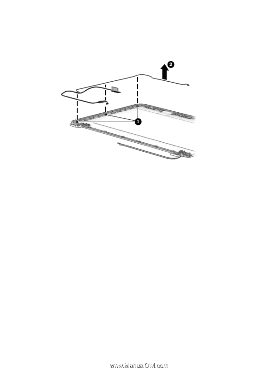
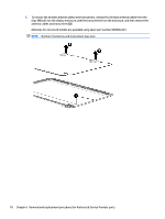
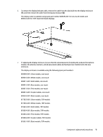
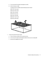
6. To remove the display/webcam cable, remove the cable from the clips built into the display enclosure (1), and then remove the cable from the display enclosure (2). The display cable is available using spare part number 809028-001 for non-touch models and 809342-001 for TOP (Touch On Panel) displays. 7. If replacing the display enclosure, be sure that the subcomponents (including the webcam/microphone module, the antenna receivers, and all associated cables and hardware) are transferred to the new enclosure. The display enclosure is available using the following spare part numbers: 809009-001: Silver models, non-touch 809010-001: White models, non-touch 809011-001: Red models, non-touch 809012-001: Blue models, non-touch 809013-001: Pink models, non-touch 809014-001: Purple models, non-touch 809343-001: Black models, non-touch 817835-001: Silver models, TOP models 817836-001: White models, TOP models 818653-001: Red models, TOP models 818654-001: Blue models, TOP models 818655-001: Pink models, TOP models 818656-001: Purple models, TOP models 818657-001: Black models, TOP models Component replacement procedures 79
-
 1
1 -
2
-
3
-
4
-
5
-
6
-
7
-
8
-
9
-
10
-
11
-
12
-
13
-
14
-
15
-
16
-
17
-
18
-
19
-
20
-
21
-
22
-
23
-
24
-
25
-
26
-
27
-
28
-
29
-
30
-
31
-
32
-
33
-
34
-
35
-
36
-
37
-
38
-
39
-
40
-
41
-
42
-
43
-
44
-
45
-
46
-
47
-
48
-
49
-
50
-
51
-
52
-
53
-
54
-
55
-
56
-
57
-
58
-
59
-
60
-
61
-
62
-
63
-
64
-
65
-
66
-
67
-
68
-
69
-
70
-
71
-
72
-
73
-
74
-
75
-
76
-
77
-
78
-
79
-
80
-
81
-
 82
82 -
 83
83 -
 84
84 -
 85
85 -
 86
86 -
 87
87 -
 88
88 -
 89
89 -
 90
90 -
 91
91 -
 92
92 -
93
-
94
-
95
-
96
-
97
-
98
-
99
-
100
-
101
-
102
-
103
-
104
-
105
-
106
-
107
-
108
-
109
-
110
-
111
-
112
-
113
-
114
-
115
-
116
-
117
-
118
-
119
-
120
-
121
-
122
-
123
-
124
-
125
-
126
-
127
-
128
-
129
-
130
-
131
-
132
-
133
-
134
-
135
-
136
-
137
-
138
-
139
-
140
-
141
-
142
 |
 |