HP Pavilion 15-n100 Maintenance and Service Guide - Page 108
If it is necessary to replace the display bezel or any of the display assembly subcomponents
 |
View all HP Pavilion 15-n100 manuals
Add to My Manuals
Save this manual to your list of manuals |
Page 108 highlights
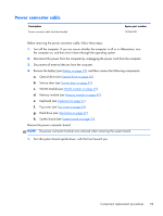
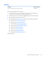
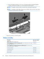
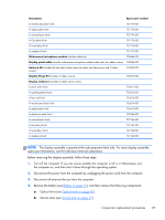
c. WLAN module (see WLAN module on page 49). d. Memory module (see Memory module on page 47). e. Keyboard (see Keyboard on page 57). f. Top cover (see Top cover on page 63). g. Hard drive (see Hard drive on page 67). h. System board (see System board on page 77). Remove the display assembly: 1. Remove the three Phillips M2.5×6.5 screws (1) and (2) that secure the display assembly to the base enclosure. 2. Remove the display assembly (3). 3. If it is necessary to replace the display bezel or any of the display assembly subcomponents: a. Remove the two display bezel screw covers (1) and the two Phillips M2.5×5.0 screws (2) that secure the display bezel to the display assembly. The display bezel screw covers are included in the display bezel spare part kit, spare part number 676644-001, and in all display assembly subcomponent spare part kits. b. Flex the inside edges of the bottom edge (3), the left and right sides (4), and the top edge (5) of the display bezel until the bezel disengages from the display enclosure. 98 Chapter 6 Removal and replacement procedures for Authorized Service Provider parts
-
 1
1 -
2
-
3
-
4
-
5
-
6
-
7
-
8
-
9
-
10
-
11
-
12
-
13
-
14
-
15
-
16
-
17
-
18
-
19
-
20
-
21
-
22
-
23
-
24
-
25
-
26
-
27
-
28
-
29
-
30
-
31
-
32
-
33
-
34
-
35
-
36
-
37
-
38
-
39
-
40
-
41
-
42
-
43
-
44
-
45
-
46
-
47
-
48
-
49
-
50
-
51
-
52
-
53
-
54
-
55
-
56
-
57
-
58
-
59
-
60
-
61
-
62
-
63
-
64
-
65
-
66
-
67
-
68
-
69
-
70
-
71
-
72
-
73
-
74
-
75
-
76
-
77
-
78
-
79
-
80
-
81
-
82
-
83
-
84
-
85
-
86
-
87
-
88
-
89
-
90
-
91
-
92
-
93
-
94
-
95
-
96
-
97
-
98
-
99
-
100
-
101
-
102
-
 103
103 -
 104
104 -
 105
105 -
 106
106 -
 107
107 -
 108
108 -
 109
109 -
 110
110 -
 111
111 -
 112
112 -
 113
113 -
114
-
115
-
116
-
117
-
118
-
119
-
120
-
121
-
122
-
123
-
124
-
125
-
126
-
127
-
128
-
129
-
130
-
131
-
132
-
133
-
134
-
135
-
136
-
137
-
138
-
139
-
140
-
141
 |
 |
