HP Pavilion 17-ab200 Maintenance and Service Guide - Page 49
Press the release tab, and remove the bezel from the tab side
 |
View all HP Pavilion 17-ab200 manuals
Add to My Manuals
Save this manual to your list of manuals |
Page 49 highlights
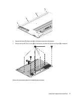
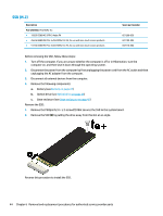
2. If it is necessary to disassemble the optical drive, perform the following steps: a. Remove the M2.0 × 2.5 screw (1) that secures the optical drive bracket to the optical drive, and then remove the bracket (2) from the optical drive. b. Press the release tab (1) and remove the bezel from the tab side (2). c. Remove the bezel (3) from the optical drive. Reverse this procedure to install the optical drive. Component replacement procedures 39
-
 1
1 -
2
-
3
-
4
-
5
-
6
-
7
-
8
-
9
-
10
-
11
-
12
-
13
-
14
-
15
-
16
-
17
-
18
-
19
-
20
-
21
-
22
-
23
-
24
-
25
-
26
-
27
-
28
-
29
-
30
-
31
-
32
-
33
-
34
-
35
-
36
-
37
-
38
-
39
-
40
-
41
-
42
-
43
-
 44
44 -
 45
45 -
 46
46 -
 47
47 -
 48
48 -
 49
49 -
 50
50 -
 51
51 -
 52
52 -
 53
53 -
 54
54 -
55
-
56
-
57
-
58
-
59
-
60
-
61
-
62
-
63
-
64
-
65
-
66
-
67
-
68
-
69
-
70
-
71
-
72
-
73
-
74
-
75
-
76
-
77
-
78
-
79
-
80
-
81
-
82
-
83
-
84
-
85
-
86
-
87
-
88
-
89
-
90
-
91
-
92
-
93
-
94
-
95
-
96
-
97
-
98
-
99
-
100
-
101
-
102
-
103
-
104
 |
 |

2.
If it is necessary to disassemble the optical drive, perform the following steps:
a.
Remove the M2.0 × 2.5 screw
(1)
that secures the optical drive bracket to the optical drive, and
then remove the bracket
(2)
from the optical drive.
b.
Press the release tab
(1)
and remove the bezel from the tab side
(2)
.
c.
Remove the bezel
(3)
from the optical drive.
Reverse this procedure to install the optical drive.
Component replacement procedures
39