HP Pavilion 17-ab200 Maintenance and Service Guide - Page 79
Heat sink for discrete graphics memory see
 |
View all HP Pavilion 17-ab200 manuals
Add to My Manuals
Save this manual to your list of manuals |
Page 79 highlights
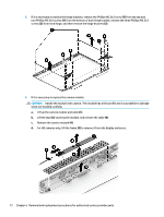
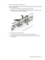
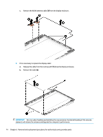
Description ● Non-touch screen, UHD, AG, UWVA, 300 eDP, 1.3PSR, Flat PA ● Touch screen, FHD, AG Spare part number 853322-001 857840-001 IMPORTANT: Make special note of each screw and screw lock size and location during removal and replacement. Before removing the display assembly, follow these steps: 1. Shut down the computer. 2. Disconnect the power from the computer by first unplugging the power cord from the AC outlet and then unplugging the AC adapter from the computer. 3. Disconnect all external devices connected to the computer. 4. Remove the following components: a. Battery (see Battery on page 37) b. Optical drive (see Optical drive on page 38) c. Base enclosure (see Base enclosure on page 40) d. Hard drive (see Hard drive on page 42) e. SSD (see SSD (M.2) on page 44) f. Disconnect the WLAN cable (see WLAN module on page 47) g. Right speaker (see Right speaker on page 49) h. USB board (see USB board on page 51) i. Fan (see Fan on page 52) j. Heat sink for discrete graphics memory (see Heat sink for discrete graphics memory on page 53) k. Left speaker (see Left speaker on page 55) l. System board (see System board on page 59) Remove the display assembly: 1. Remove the two Phillips screws from the right hinge and the two Phillips screws from the left hinge (1), open the hinges (2) as wide as possible, and then remove the display assembly (3). Component replacement procedures 69
-
 1
1 -
2
-
3
-
4
-
5
-
6
-
7
-
8
-
9
-
10
-
11
-
12
-
13
-
14
-
15
-
16
-
17
-
18
-
19
-
20
-
21
-
22
-
23
-
24
-
25
-
26
-
27
-
28
-
29
-
30
-
31
-
32
-
33
-
34
-
35
-
36
-
37
-
38
-
39
-
40
-
41
-
42
-
43
-
44
-
45
-
46
-
47
-
48
-
49
-
50
-
51
-
52
-
53
-
54
-
55
-
56
-
57
-
58
-
59
-
60
-
61
-
62
-
63
-
64
-
65
-
66
-
67
-
68
-
69
-
70
-
71
-
72
-
73
-
 74
74 -
 75
75 -
 76
76 -
 77
77 -
 78
78 -
 79
79 -
 80
80 -
 81
81 -
 82
82 -
 83
83 -
 84
84 -
85
-
86
-
87
-
88
-
89
-
90
-
91
-
92
-
93
-
94
-
95
-
96
-
97
-
98
-
99
-
100
-
101
-
102
-
103
-
104
 |
 |
