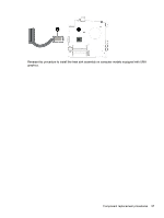
HP Pavilion Notebook - 14-v124ca HP Pavilion 14 Notebook PC HP Pavilion 14 Tou - Page 65
Before removing the heat sink assembly, follow these steps
 |
View all HP Pavilion Notebook - 14-v124ca manuals
Add to My Manuals
Save this manual to your list of manuals |
Page 65 highlights
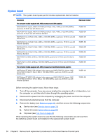
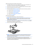
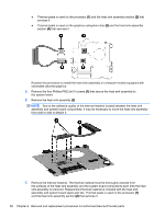
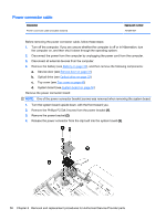
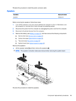
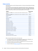
Before removing the heat sink assembly, follow these steps: 1. Turn off the computer. If you are unsure whether the computer is off or in Hibernation, turn the computer on, and then shut it down through the operating system. 2. Disconnect the power from the computer by unplugging the power cord from the computer. 3. Disconnect all external devices from the computer. 4. Remove the battery (see Battery on page 30), and then remove the following components: a. Service door (see Service door on page 31) b. Optical drive (see Optical drive on page 33) c. Top cover (see Top cover on page 40) d. System board (see System board on page 50) e. Fan (see Fan on page 53) Remove the heat sink assembly: 1. Turn the system board upside down, with the front toward you. NOTE: Steps 2 through 4 apply to computer models equipped with switchable discrete graphics. See steps 5 through 7 for heat sink assembly removal information for computer models equipped with UMA graphics. 2. Remove the four Phillips M2.5x4.0 screws (1) and the three Phillips PM2.5x4.0 screws (2) that secure the heat sink assembly to the system board. 3. Remove the heat sink assembly (3) from the system board. NOTE: Due to the adhesive quality of the thermal material located between the heat sink assembly and the system board components, it may be necessary to move the heat sink assembly from side to side to detach it. 4. Remove the thermal material. The thermal material must be thoroughly cleaned from the surfaces of the heat sink assembly and the system board components each time the heat sink assembly is removed. Replacement thermal material is included with the heat sink assembly and system board spare part kits. Component replacement procedures 55
-
 1
1 -
2
-
3
-
4
-
5
-
6
-
7
-
8
-
9
-
10
-
11
-
12
-
13
-
14
-
15
-
16
-
17
-
18
-
19
-
20
-
21
-
22
-
23
-
24
-
25
-
26
-
27
-
28
-
29
-
30
-
31
-
32
-
33
-
34
-
35
-
36
-
37
-
38
-
39
-
40
-
41
-
42
-
43
-
44
-
45
-
46
-
47
-
48
-
49
-
50
-
51
-
52
-
53
-
54
-
55
-
56
-
57
-
58
-
59
-
 60
60 -
 61
61 -
 62
62 -
 63
63 -
 64
64 -
 65
65 -
 66
66 -
 67
67 -
 68
68 -
 69
69 -
 70
70 -
71
-
72
-
73
-
74
-
75
-
76
-
77
-
78
-
79
-
80
-
81
-
82
-
83
-
84
-
85
-
86
-
87
-
88
-
89
-
90
-
91
-
92
-
93
-
94
-
95
-
96
 |
 |