HP Pavilion Sleekbook 14-b015dx HP Pavilion Sleekbook 14 and HP Pavilion Ultra - Page 84
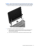
Remove the display assembly see
 |
View all HP Pavilion Sleekbook 14-b015dx manuals
Add to My Manuals
Save this manual to your list of manuals |
Page 84 highlights
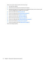
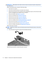
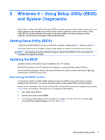
IMPORTANT: Make special note of each screw and screw lock size and location during removal and replacement. Before removing the power connector, follow these steps: 1. Shut down the computer. 2. Disconnect all external devices connected to the computer. 3. Disconnect the power from the computer by first unplugging the power cord from the AC outlet and then unplugging the AC adapter from the computer. 4. Remove the battery (see Battery on page 35). 5. Remove the keyboard (see Keyboard on page 39). 6. Remove the top cover (see Top cover on page 43). 7. Remove the hard drive (see Hard drive on page 47). 8. Remove the USB board (see USB board/audio jack on page 50). 9. Remove the WLAN (see WLAN module on page 51). 10. Remove the system board (see System board on page 54). 11. Remove the display assembly (see Display panel on page 37). Remove the power connector: NOTE: The power connector screw and bracket were removed during the process to remove the system board. ▲ Lift out the power connector to remove it from the base enclosure. Reverse these procedures to replace the power connector. 76 Chapter 4 Removal and replacement procedures
-
 1
1 -
2
-
3
-
4
-
5
-
6
-
7
-
8
-
9
-
10
-
11
-
12
-
13
-
14
-
15
-
16
-
17
-
18
-
19
-
20
-
21
-
22
-
23
-
24
-
25
-
26
-
27
-
28
-
29
-
30
-
31
-
32
-
33
-
34
-
35
-
36
-
37
-
38
-
39
-
40
-
41
-
42
-
43
-
44
-
45
-
46
-
47
-
48
-
49
-
50
-
51
-
52
-
53
-
54
-
55
-
56
-
57
-
58
-
59
-
60
-
61
-
62
-
63
-
64
-
65
-
66
-
67
-
68
-
69
-
70
-
71
-
72
-
73
-
74
-
75
-
76
-
77
-
78
-
 79
79 -
 80
80 -
 81
81 -
 82
82 -
 83
83 -
 84
84 -
 85
85 -
 86
86 -
 87
87 -
 88
88 -
 89
89 -
90
-
91
-
92
-
93
-
94
-
95
-
96
-
97
-
98
-
99
-
100
-
101
-
102
-
103
-
104
-
105
-
106
-
107
-
108
-
109
-
110
 |
 |