HP Pavilion TouchSmart 11-e110nr HP Pavilion 11 Notebook PC HP Pavilion TouchS - Page 75
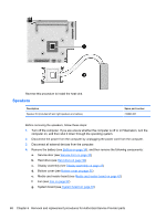
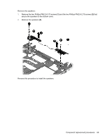
Remove the three Phillips PM2.0×4.5 screws, built into the system board.
 |
View all HP Pavilion TouchSmart 11-e110nr manuals
Add to My Manuals
Save this manual to your list of manuals |
Page 75 highlights
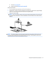
NOTE: When replacing the system board, be sure that the following components are removed from the defective system board and installed on the replacement system board: ● WLAN module (see WLAN module on page 38) ● Memory module (see Memory module on page 40) ● Heat sink (see Heat sink on page 66) Remove the system board: 1. Disconnect the monitor connector board cable (1) from the system board. 2. Disconnect the speaker cable (2) from the system board. 3. Release the speaker cable from the tabs (3) built into the system board. 4. Remove the three Phillips PM2.0×4.5 screws (1) that secure the system board to the top cover. 5. Lift the left side of the system board (2) until it rests at an angle. Component replacement procedures 65
-
 1
1 -
2
-
3
-
4
-
5
-
6
-
7
-
8
-
9
-
10
-
11
-
12
-
13
-
14
-
15
-
16
-
17
-
18
-
19
-
20
-
21
-
22
-
23
-
24
-
25
-
26
-
27
-
28
-
29
-
30
-
31
-
32
-
33
-
34
-
35
-
36
-
37
-
38
-
39
-
40
-
41
-
42
-
43
-
44
-
45
-
46
-
47
-
48
-
49
-
50
-
51
-
52
-
53
-
54
-
55
-
56
-
57
-
58
-
59
-
60
-
61
-
62
-
63
-
64
-
65
-
66
-
67
-
68
-
69
-
 70
70 -
 71
71 -
 72
72 -
 73
73 -
 74
74 -
 75
75 -
 76
76 -
 77
77 -
 78
78 -
 79
79 -
 80
80 -
81
-
82
-
83
-
84
-
85
-
86
-
87
-
88
-
89
-
90
-
91
-
92
-
93
-
94
-
95
-
96
-
97
-
98
-
99
-
100
-
101
-
102
-
103
-
104
 |
 |

NOTE:
When replacing the system board, be sure that the following components are removed from
the defective system board and installed on the replacement system board:
●
WLAN module (see
WLAN module
on page
38
)
●
Memory module (see
Memory module
on page
40
)
●
Heat sink (see
Heat sink
on page
66
)
Remove the system board:
1.
Disconnect the monitor connector board cable
(1)
from the system board.
2.
Disconnect the speaker cable
(2)
from the system board.
3.
Release the speaker cable from the tabs
(3)
built into the system board.
4.
Remove the three Phillips PM2.0×4.5 screws
(1)
that secure the system board to the top cover.
5.
Lift the left side of the system board
(2)
until it rests at an angle.
Component replacement procedures
65