HP Pavilion TouchSmart 15-b100 HP Pavilion TouchSmart Sleekbook 15 and HP Pavi - Page 68
Display assembly, Shut down the computer.
 |
View all HP Pavilion TouchSmart 15-b100 manuals
Add to My Manuals
Save this manual to your list of manuals |
Page 68 highlights
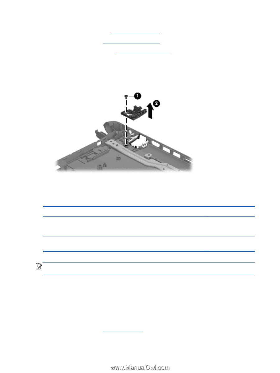
8. Remove the USB board (see USB board on page 41). 9. Remove the WLAN (see WLAN module on page 42). 10. Remove the system board (see System board on page 45). Remove the RJ-45 cover: 1. Remove the screw (1) that secures the RJ-45 cover to the base enclosure. 2. Remove the RJ-45 cover (2) from the base enclosure. Reverse these procedures to replace the RJ-45 cover. Display assembly Description Spare part number Display assembly: TouchScreen and non-TouchScreen display assemblies are available. The TouchScreen display assembly is spared only as a whole unit replacement component. The non-TouchScreen display assembly is spared only at the subcomponent level. For non-TouchScreen display assembly spare part information, see the individual removal subsections. 15.6-in, WLED, SVA, HD, BrightView, TouchScreen display assembly in sparkling black finish (includes display panel cable, webcam/microphone module, and 2 wireless antenna cables) 709171-001 IMPORTANT: Make special note of each screw and screw lock size and location during removal and replacement. Before removing the display assembly, follow these steps: 1. Shut down the computer. 2. Disconnect all external devices connected to the computer. 3. Disconnect the power from the computer by first unplugging the power cord from the AC outlet and then unplugging the AC adapter from the computer. 4. Remove the battery (see Battery on page 30). 60 Chapter 4 Removal and replacement procedures
-
 1
1 -
2
-
3
-
4
-
5
-
6
-
7
-
8
-
9
-
10
-
11
-
12
-
13
-
14
-
15
-
16
-
17
-
18
-
19
-
20
-
21
-
22
-
23
-
24
-
25
-
26
-
27
-
28
-
29
-
30
-
31
-
32
-
33
-
34
-
35
-
36
-
37
-
38
-
39
-
40
-
41
-
42
-
43
-
44
-
45
-
46
-
47
-
48
-
49
-
50
-
51
-
52
-
53
-
54
-
55
-
56
-
57
-
58
-
59
-
60
-
61
-
62
-
 63
63 -
 64
64 -
 65
65 -
 66
66 -
 67
67 -
 68
68 -
 69
69 -
 70
70 -
 71
71 -
 72
72 -
 73
73 -
74
-
75
-
76
-
77
-
78
-
79
-
80
-
81
-
82
-
83
-
84
-
85
-
86
-
87
-
88
-
89
-
90
-
91
-
92
-
93
-
94
-
95
-
96
 |
 |