HP Pavilion dv7-3100 HP Pavilion dv7 Entertainment PC - Maintenance and Servic - Page 55
Switch cover and keyboard
 |
View all HP Pavilion dv7-3100 manuals
Add to My Manuals
Save this manual to your list of manuals |
Page 55 highlights
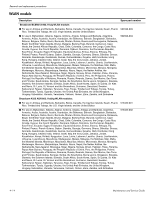
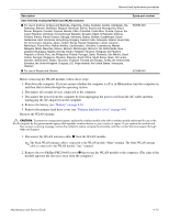
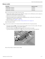
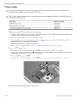
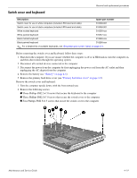
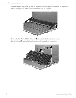
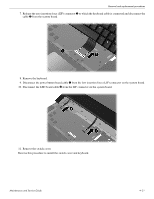
Switch cover and keyboard Removal and replacement procedures Description: Spare part number Switch cover for use in white computers (includes LED board and cable) 516300-001 Switch cover for use in black computers (includes LED board and cable) 519269-001 White molded keyboard 516356-xxx White painted keyboard 516357-xxx Black molded keyboard 519265-xxx Black painted keyboard 519266-xxx ✎ For a detailed list of available keyboards, see "Sequential part number listing" on page 3-11. Before removing the switch cover and keyboard, follow these steps: 1. Shut down the computer. If you are unsure whether the computer is off or in Hibernation, turn the computer on, and then shut it down through the operating system. 2. Disconnect all external devices connected to the computer. 3. Disconnect the power from the computer by first unplugging the power cord from the AC outlet and then unplugging the AC adapter from the computer. 4. Remove the battery (see "Battery" on page 4-6). 5. Remove the primary hard drive cover (see "Primary hard drive cover" on page 4-9). Remove the switch cover and keyboard: 1. Turn the computer upside down, with the front toward you. 2. Remove the following screws: 1 Three Phillips PM2.5×7.0 screws that secure the keyboard to the computer 2 Three Phillips PM2.5×7.0 screws that secure the switch cover to the computer 3 Four Phillips PM2.5×4.5 screws that secure the switch cover to the computer Maintenance and Service Guide 4-19
-
 1
1 -
2
-
3
-
4
-
5
-
6
-
7
-
8
-
9
-
10
-
11
-
12
-
13
-
14
-
15
-
16
-
17
-
18
-
19
-
20
-
21
-
22
-
23
-
24
-
25
-
26
-
27
-
28
-
29
-
30
-
31
-
32
-
33
-
34
-
35
-
36
-
37
-
38
-
39
-
40
-
41
-
42
-
43
-
44
-
45
-
46
-
47
-
48
-
49
-
 50
50 -
 51
51 -
 52
52 -
 53
53 -
 54
54 -
 55
55 -
 56
56 -
 57
57 -
 58
58 -
 59
59 -
 60
60 -
61
-
62
-
63
-
64
-
65
-
66
-
67
-
68
-
69
-
70
-
71
-
72
-
73
-
74
-
75
-
76
-
77
-
78
-
79
-
80
-
81
-
82
-
83
-
84
-
85
-
86
-
87
-
88
-
89
-
90
-
91
-
92
-
93
-
94
-
95
-
96
-
97
-
98
-
99
-
100
-
101
-
102
-
103
-
104
-
105
-
106
-
107
-
108
-
109
-
110
-
111
-
112
-
113
-
114
-
115
-
116
-
117
-
118
-
119
-
120
-
121
-
122
-
123
-
124
-
125
-
126
-
127
-
128
-
129
-
130
-
131
-
132
-
133
-
134
-
135
-
136
-
137
-
138
-
139
-
140
 |
 |
