HP Pavilion dv7-3100 HP Pavilion dv7 Entertainment PC - Maintenance and Servic - Page 75
Lift the system board to the right and up and out of the base enclosure
 |
View all HP Pavilion dv7-3100 manuals
Add to My Manuals
Save this manual to your list of manuals |
Page 75 highlights
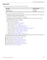
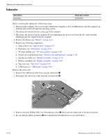
Removal and replacement procedures 3. Remove the three Phillips PM2.5×5.0 screws that secure the system board to the base enclosure. 4. Lift up on the right side 1 of the system board slightly, and then unplug the bottom power connector cable from the connector on the bottom of the system board 2. 5. Lift the system board to the right and up and out of the base enclosure 3. 6. If it is necessary to remove the optical drive board from the system board, pull the optical drive board straight off the system board. The optical drive board is available using spare part number 519481-001. Reverse this procedure to install the system board. Maintenance and Service Guide 4-39
-
 1
1 -
2
-
3
-
4
-
5
-
6
-
7
-
8
-
9
-
10
-
11
-
12
-
13
-
14
-
15
-
16
-
17
-
18
-
19
-
20
-
21
-
22
-
23
-
24
-
25
-
26
-
27
-
28
-
29
-
30
-
31
-
32
-
33
-
34
-
35
-
36
-
37
-
38
-
39
-
40
-
41
-
42
-
43
-
44
-
45
-
46
-
47
-
48
-
49
-
50
-
51
-
52
-
53
-
54
-
55
-
56
-
57
-
58
-
59
-
60
-
61
-
62
-
63
-
64
-
65
-
66
-
67
-
68
-
69
-
 70
70 -
 71
71 -
 72
72 -
 73
73 -
 74
74 -
 75
75 -
 76
76 -
 77
77 -
 78
78 -
 79
79 -
 80
80 -
81
-
82
-
83
-
84
-
85
-
86
-
87
-
88
-
89
-
90
-
91
-
92
-
93
-
94
-
95
-
96
-
97
-
98
-
99
-
100
-
101
-
102
-
103
-
104
-
105
-
106
-
107
-
108
-
109
-
110
-
111
-
112
-
113
-
114
-
115
-
116
-
117
-
118
-
119
-
120
-
121
-
122
-
123
-
124
-
125
-
126
-
127
-
128
-
129
-
130
-
131
-
132
-
133
-
134
-
135
-
136
-
137
-
138
-
139
-
140
 |
 |
Removal and replacement procedures
Maintenance and Service Guide
4–39
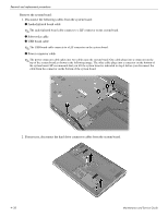
3. Remove the three Phillips PM2.5×5.0 screws that secure the system board to the base enclosure.
4.
Lift up on the right side
1
of the system board slightly, and then unplug the bottom power connector cable from
the connector on the bottom of the system board
2
.
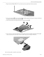
5. Lift the system board to the right and up and out of the base enclosure
3
.
6. If it is necessary to remove the optical drive board from the system board, pull the optical drive board straight
off the system board. The optical drive board is available using spare part number 519481-001.
Reverse this procedure to install the system board.