HP Pavilion dv7-3100 HP Pavilion dv7 Entertainment PC - Maintenance and Servic - Page 63
Release the webcam/microphone module, secures the module to the display bezel.
 |
View all HP Pavilion dv7-3100 manuals
Add to My Manuals
Save this manual to your list of manuals |
Page 63 highlights
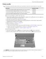
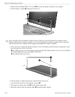
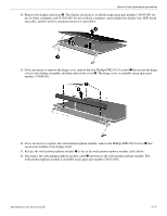
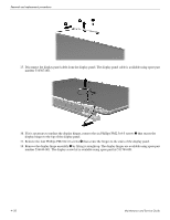
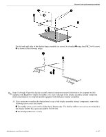
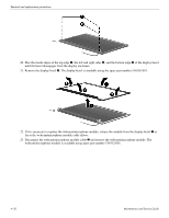
Removal and replacement procedures 10. Remove the display enclosure 4. The display enclosure is available using spare part number 516443-001 for use in white computers and 519262-001 for use in black computers, and includes the display logo LED board and cable, and the wireless antenna transceivers and cables. 11. If it is necessary to remove the hinge cover, remove the four Phillips PM2.5×5.0 screws 1 that secure the hinge cover to the display assembly, and then remove the cover 2. The hinge cover is available using spare part number 537844-001. 12. If it is necessary to replace the webcam/microphone module, remove the Phillips PM2.0×4.0 screw 1 that secures the module to the display bezel. 13. Release the webcam/microphone module 2 as far as the webcam/microphone module cable allows. 14. Disconnect the webcam/microphone module cable 3 and remove the webcam/microphone module. The webcam/microphone module is available using spare part number 516312-001. Maintenance and Service Guide 4-27
-
 1
1 -
2
-
3
-
4
-
5
-
6
-
7
-
8
-
9
-
10
-
11
-
12
-
13
-
14
-
15
-
16
-
17
-
18
-
19
-
20
-
21
-
22
-
23
-
24
-
25
-
26
-
27
-
28
-
29
-
30
-
31
-
32
-
33
-
34
-
35
-
36
-
37
-
38
-
39
-
40
-
41
-
42
-
43
-
44
-
45
-
46
-
47
-
48
-
49
-
50
-
51
-
52
-
53
-
54
-
55
-
56
-
57
-
 58
58 -
 59
59 -
 60
60 -
 61
61 -
 62
62 -
 63
63 -
 64
64 -
 65
65 -
 66
66 -
 67
67 -
 68
68 -
69
-
70
-
71
-
72
-
73
-
74
-
75
-
76
-
77
-
78
-
79
-
80
-
81
-
82
-
83
-
84
-
85
-
86
-
87
-
88
-
89
-
90
-
91
-
92
-
93
-
94
-
95
-
96
-
97
-
98
-
99
-
100
-
101
-
102
-
103
-
104
-
105
-
106
-
107
-
108
-
109
-
110
-
111
-
112
-
113
-
114
-
115
-
116
-
117
-
118
-
119
-
120
-
121
-
122
-
123
-
124
-
125
-
126
-
127
-
128
-
129
-
130
-
131
-
132
-
133
-
134
-
135
-
136
-
137
-
138
-
139
-
140
 |
 |
