HP Pavilion ze2500 HP Pavilion ze2000 Notebook PC, Compaq Presario M2000 Noteb - Page 151
toward the rear panel, until it disconnects from the system board.
 |
View all HP Pavilion ze2500 manuals
Add to My Manuals
Save this manual to your list of manuals |
Page 151 highlights
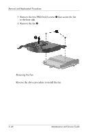
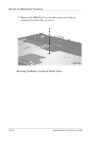
Removal and Replacement Procedures 4. Turn the top cover upside down with the front panel toward you. 5. Remove the PM2.0×4.0 screw 1 that secures the battery connector board to the top cover. 6. Slide the battery connector board 2 toward the rear panel until it disconnects from the system board. 7. Remove the battery connector board 3. Removing the Battery Connector Board Reverse the above procedure to install the the battery connector board. Maintenance and Service Guide 5-51
-
 1
1 -
2
-
3
-
4
-
5
-
6
-
7
-
8
-
9
-
10
-
11
-
12
-
13
-
14
-
15
-
16
-
17
-
18
-
19
-
20
-
21
-
22
-
23
-
24
-
25
-
26
-
27
-
28
-
29
-
30
-
31
-
32
-
33
-
34
-
35
-
36
-
37
-
38
-
39
-
40
-
41
-
42
-
43
-
44
-
45
-
46
-
47
-
48
-
49
-
50
-
51
-
52
-
53
-
54
-
55
-
56
-
57
-
58
-
59
-
60
-
61
-
62
-
63
-
64
-
65
-
66
-
67
-
68
-
69
-
70
-
71
-
72
-
73
-
74
-
75
-
76
-
77
-
78
-
79
-
80
-
81
-
82
-
83
-
84
-
85
-
86
-
87
-
88
-
89
-
90
-
91
-
92
-
93
-
94
-
95
-
96
-
97
-
98
-
99
-
100
-
101
-
102
-
103
-
104
-
105
-
106
-
107
-
108
-
109
-
110
-
111
-
112
-
113
-
114
-
115
-
116
-
117
-
118
-
119
-
120
-
121
-
122
-
123
-
124
-
125
-
126
-
127
-
128
-
129
-
130
-
131
-
132
-
133
-
134
-
135
-
136
-
137
-
138
-
139
-
140
-
141
-
142
-
143
-
144
-
145
-
 146
146 -
 147
147 -
 148
148 -
 149
149 -
 150
150 -
 151
151 -
 152
152 -
 153
153 -
 154
154 -
 155
155 -
 156
156 -
157
-
158
-
159
-
160
-
161
-
162
-
163
-
164
-
165
-
166
-
167
-
168
-
169
-
170
-
171
-
172
-
173
-
174
-
175
-
176
-
177
-
178
-
179
-
180
-
181
-
182
-
183
-
184
-
185
-
186
-
187
-
188
-
189
-
190
-
191
-
192
-
193
-
194
-
195
-
196
-
197
-
198
-
199
-
200
-
201
-
202
-
203
-
204
-
205
-
206
-
207
-
208
-
209
-
210
-
211
-
212
-
213
-
214
-
215
-
216
-
217
-
218
-
219
-
220
-
221
-
222
-
223
-
224
-
225
-
226
-
227
-
228
-
229
-
230
-
231
-
232
-
233
-
234
-
235
-
236
-
237
-
238
-
239
 |
 |

Removal and Replacement Procedures
Maintenance and Service Guide
5–51
4. Turn the top cover upside down with the front panel
toward you.
5. Remove the PM2.0×4.0 screw
1
that secures the battery
connector board to the top cover.
6. Slide the battery connector board
2
toward the rear panel
until it disconnects from the system board.
7. Remove the battery connector board
3
.
Removing the Battery Connector Board
Reverse the above procedure to install the the battery connector
board.