HP Pavilion ze2500 HP Pavilion ze2000 Notebook PC, Compaq Presario M2000 Noteb - Page 152
Power Connector Board, Power Connector Board Spare Part Number Information
 |
View all HP Pavilion ze2500 manuals
Add to My Manuals
Save this manual to your list of manuals |
Page 152 highlights
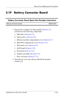
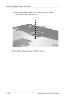
Removal and Replacement Procedures 5.20 Power Connector Board Power Connector Board Spare Part Number Information Power connector board 382414-001 1. Prepare the computer for disassembly (Section 5.3) and remove the following components: a. Hard drive (Section 5.4) b. Optical drive (Section 5.6) c. Memory module compartment cover (Section 5.7) d. Mini PCI compartment cover (Section 5.8) e. Keyboard cover (Section 5.9) f. LED board (Section 5.10) g. Keyboard (Section 5.11) h. Display assembly (Section 5.12) i. Base enclosure (Section 5.13) 5-52 Maintenance and Service Guide
-
 1
1 -
2
-
3
-
4
-
5
-
6
-
7
-
8
-
9
-
10
-
11
-
12
-
13
-
14
-
15
-
16
-
17
-
18
-
19
-
20
-
21
-
22
-
23
-
24
-
25
-
26
-
27
-
28
-
29
-
30
-
31
-
32
-
33
-
34
-
35
-
36
-
37
-
38
-
39
-
40
-
41
-
42
-
43
-
44
-
45
-
46
-
47
-
48
-
49
-
50
-
51
-
52
-
53
-
54
-
55
-
56
-
57
-
58
-
59
-
60
-
61
-
62
-
63
-
64
-
65
-
66
-
67
-
68
-
69
-
70
-
71
-
72
-
73
-
74
-
75
-
76
-
77
-
78
-
79
-
80
-
81
-
82
-
83
-
84
-
85
-
86
-
87
-
88
-
89
-
90
-
91
-
92
-
93
-
94
-
95
-
96
-
97
-
98
-
99
-
100
-
101
-
102
-
103
-
104
-
105
-
106
-
107
-
108
-
109
-
110
-
111
-
112
-
113
-
114
-
115
-
116
-
117
-
118
-
119
-
120
-
121
-
122
-
123
-
124
-
125
-
126
-
127
-
128
-
129
-
130
-
131
-
132
-
133
-
134
-
135
-
136
-
137
-
138
-
139
-
140
-
141
-
142
-
143
-
144
-
145
-
146
-
 147
147 -
 148
148 -
 149
149 -
 150
150 -
 151
151 -
 152
152 -
 153
153 -
 154
154 -
 155
155 -
 156
156 -
 157
157 -
158
-
159
-
160
-
161
-
162
-
163
-
164
-
165
-
166
-
167
-
168
-
169
-
170
-
171
-
172
-
173
-
174
-
175
-
176
-
177
-
178
-
179
-
180
-
181
-
182
-
183
-
184
-
185
-
186
-
187
-
188
-
189
-
190
-
191
-
192
-
193
-
194
-
195
-
196
-
197
-
198
-
199
-
200
-
201
-
202
-
203
-
204
-
205
-
206
-
207
-
208
-
209
-
210
-
211
-
212
-
213
-
214
-
215
-
216
-
217
-
218
-
219
-
220
-
221
-
222
-
223
-
224
-
225
-
226
-
227
-
228
-
229
-
230
-
231
-
232
-
233
-
234
-
235
-
236
-
237
-
238
-
239
 |
 |

5–52
Maintenance and Service Guide
Removal and Replacement Procedures
5.20
Power Connector Board
1. Prepare the computer for disassembly (
Section 5.3
)
and remove the following components:
a.
Hard drive (
Section 5.4
)
b.
Optical drive (
Section 5.6
)
c.
Memory module compartment cover (
Section 5.7
)
d.
Mini PCI compartment cover (
Section 5.8
)
e.
Keyboard cover (
Section 5.9
)
f.
LED board (
Section 5.10
)
g.
Keyboard (
Section 5.11
)
h.
Display assembly (
Section 5.12
)
i.
Base enclosure (
Section 5.13
)
Power Connector Board Spare Part Number Information
Power connector board
382414-001