HP Presario 1600 Presario 1650 Series Maintenance and Service Guide - Page 49
Removing the Palmrest Cover with Touch Pad
 |
View all HP Presario 1600 manuals
Add to My Manuals
Save this manual to your list of manuals |
Page 49 highlights
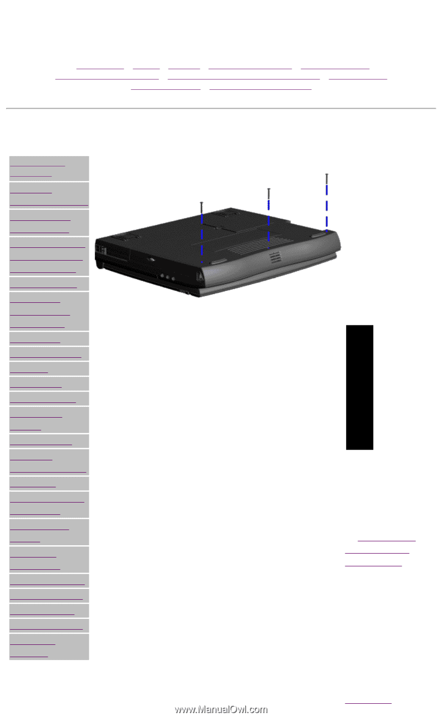
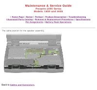
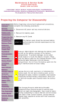
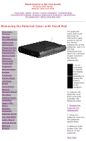
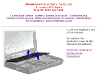
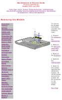
Maintenance & Service Guide Presario 1600 Series Models: 1650 and 1655 | Home Page | Notice | Preface | Product Description | Troubleshooting Illustrated Parts Catalog | Removal & Replacement Procedures | Specifications Pin Assignments | Battery Pack Operations Removing the Palmrest Cover with Touch Pad Electrostatic Discharge Service Considerations Cables and Connectors Preparing the Computer for Disassembly Battery Pack Palmrest Cover with Touch Pad Keyboard Heatspreader Modem Processor Status Panel Interface Board Hard Drives Battery Charger Board CD Drive Display Panel Assembly Upper CPU Cover Speaker Assembly Diskette Drive Fan Assembly Audio Board System Board Memory Module The palmrest cover with touch pad must be removed to gain access to any of the interior components of the computer, and it is the first component that has to be removed to gain access to the interior components. It is not necessary to remove the display panel NOTE: assembly to access the interior components of the computer. To remove the palmrest cover with touch pad, complete the following steps: 1. Prepare the computer for disassembly. 2. Close the computer and turn the computer upside down. 3. Remove three screws from the bottom of the computer. Next Step
-
 1
1 -
2
-
3
-
4
-
5
-
6
-
7
-
8
-
9
-
10
-
11
-
12
-
13
-
14
-
15
-
16
-
17
-
18
-
19
-
20
-
21
-
22
-
23
-
24
-
25
-
26
-
27
-
28
-
29
-
30
-
31
-
32
-
33
-
34
-
35
-
36
-
37
-
38
-
39
-
40
-
41
-
42
-
43
-
 44
44 -
 45
45 -
 46
46 -
 47
47 -
 48
48 -
 49
49 -
 50
50 -
 51
51 -
 52
52 -
 53
53 -
 54
54 -
55
-
56
-
57
-
58
-
59
-
60
-
61
-
62
-
63
-
64
-
65
-
66
-
67
-
68
-
69
-
70
-
71
-
72
-
73
-
74
-
75
-
76
-
77
-
78
-
79
-
80
-
81
-
82
-
83
-
84
-
85
-
86
 |
 |