HP Pro 1000 HP Pro 1005 All-in-One Business PC - Maintenance & Service - Page 76
System Board
 |
View all HP Pro 1000 manuals
Add to My Manuals
Save this manual to your list of manuals |
Page 76 highlights
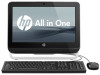
System Board Description System board Spare part number 669973-001 The system board is secured with nine screws. To remove the system board: 1. Prepare the computer for disassembly (see Preparing to Disassemble the Computer on page 34). 2. Remove the rear cover (see Rear Cover on page 35). 3. Remove the system board cover (see System Board Cover on page 60). 4. Remove the memory module (see Memory on page 62). 5. Remove the WLAN module (see WLAN Module on page 64). 6. Disconnect all cables from the system board, noting their location for reinstallation. 7. Remove the nine screws (circled in image) that secure the system board to the computer. Figure 7-36 Removing the system board 8. Lift the system board straight up and out of the computer. 68 Chapter 7 Removal and Replacement Procedures All-in One (AIO) Chassis
-
 1
1 -
2
-
3
-
4
-
5
-
6
-
7
-
8
-
9
-
10
-
11
-
12
-
13
-
14
-
15
-
16
-
17
-
18
-
19
-
20
-
21
-
22
-
23
-
24
-
25
-
26
-
27
-
28
-
29
-
30
-
31
-
32
-
33
-
34
-
35
-
36
-
37
-
38
-
39
-
40
-
41
-
42
-
43
-
44
-
45
-
46
-
47
-
48
-
49
-
50
-
51
-
52
-
53
-
54
-
55
-
56
-
57
-
58
-
59
-
60
-
61
-
62
-
63
-
64
-
65
-
66
-
67
-
68
-
69
-
70
-
 71
71 -
 72
72 -
 73
73 -
 74
74 -
 75
75 -
 76
76 -
 77
77 -
 78
78 -
 79
79 -
 80
80 -
 81
81 -
82
-
83
-
84
-
85
-
86
-
87
-
88
-
89
-
90
-
91
-
92
-
93
-
94
-
95
-
96
-
97
-
98
-
99
-
100
-
101
-
102
-
103
-
104
-
105
-
106
-
107
-
108
-
109
-
110
-
111
-
112
-
113
-
114
-
115
-
116
-
117
-
118
-
119
-
120
-
121
-
122
-
123
-
124
-
125
-
126
-
127
-
128
-
129
-
130
-
131
-
132
-
133
-
134
-
135
-
136
-
137
 |
 |
