HP Pro 3330 Micro Maintenance & Service Guide Pro 3330/3380 Microtower Pro - Page 118
Removal and Replacement Procedures - Small Form Factor SFF Chassis,
 |
View all HP Pro 3330 Micro manuals
Add to My Manuals
Save this manual to your list of manuals |
Page 118 highlights
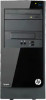
5. Open both latches of the memory module socket (1), and remove the memory module from the socket (2). Figure 8-7 Removing a DIMM NOTE: A memory module can be installed in only one way. Match the notch on the module with the tab on the memory socket. For maximum performance, populate the sockets so that the memory capacity is spread as equally as possible between Channel A and Channel B. 108 Chapter 8 Removal and Replacement Procedures - Small Form Factor (SFF) Chassis
-
 1
1 -
2
-
3
-
4
-
5
-
6
-
7
-
8
-
9
-
10
-
11
-
12
-
13
-
14
-
15
-
16
-
17
-
18
-
19
-
20
-
21
-
22
-
23
-
24
-
25
-
26
-
27
-
28
-
29
-
30
-
31
-
32
-
33
-
34
-
35
-
36
-
37
-
38
-
39
-
40
-
41
-
42
-
43
-
44
-
45
-
46
-
47
-
48
-
49
-
50
-
51
-
52
-
53
-
54
-
55
-
56
-
57
-
58
-
59
-
60
-
61
-
62
-
63
-
64
-
65
-
66
-
67
-
68
-
69
-
70
-
71
-
72
-
73
-
74
-
75
-
76
-
77
-
78
-
79
-
80
-
81
-
82
-
83
-
84
-
85
-
86
-
87
-
88
-
89
-
90
-
91
-
92
-
93
-
94
-
95
-
96
-
97
-
98
-
99
-
100
-
101
-
102
-
103
-
104
-
105
-
106
-
107
-
108
-
109
-
110
-
111
-
112
-
 113
113 -
 114
114 -
 115
115 -
 116
116 -
 117
117 -
 118
118 -
 119
119 -
 120
120 -
 121
121 -
 122
122 -
 123
123 -
124
-
125
-
126
-
127
-
128
-
129
-
130
-
131
-
132
-
133
-
134
-
135
-
136
-
137
-
138
-
139
-
140
-
141
-
142
-
143
-
144
-
145
-
146
-
147
-
148
-
149
-
150
-
151
-
152
-
153
-
154
-
155
-
156
-
157
-
158
-
159
-
160
-
161
-
162
-
163
-
164
-
165
-
166
-
167
-
168
-
169
-
170
-
171
-
172
-
173
-
174
-
175
-
176
-
177
-
178
-
179
-
180
-
181
-
182
-
183
-
184
-
185
-
186
-
187
-
188
-
189
-
190
-
191
-
192
-
193
-
194
-
195
-
196
-
197
-
198
-
199
-
200
-
201
-
202
-
203
-
204
-
205
-
206
-
207
-
208
-
209
-
210
-
211
-
212
-
213
-
214
-
215
-
216
-
217
-
218
-
219
-
220
-
221
-
222
-
223
-
224
-
225
-
226
 |
 |

5.
Open both latches of the memory module socket
(1)
, and remove the memory module from the
socket
(2)
.
Figure 8-7
Removing a DIMM
NOTE:
A memory module can be installed in only one way. Match the notch on the module
with the tab on the memory socket.
For maximum performance, populate the sockets so that the memory capacity is spread as
equally as possible between Channel A and Channel B.
108
Chapter 8
Removal and Replacement Procedures – Small Form Factor (SFF) Chassis