HP Pro 3335 Micro Maintenance & Service Guide Pro 3330/3380 Microtower Pro - Page 106
Power Supply, WARNING,
 |
View all HP Pro 3335 Micro manuals
Add to My Manuals
Save this manual to your list of manuals |
Page 106 highlights
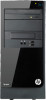
Power Supply Description Power supply, 300W Power supply, 300W, 85% efficient Power supply, 250W, PFC Spare part number 656721-001 575437-001 508466-001 WARNING! Voltage is always present on the system board when the computer is plugged into an active AC outlet. To avoid possible personal injury and damage to the equipment the power cord should be disconnected from the computer and/or the AC outlet before opening the computer. NOTE: When installing a new power supply, be sure to set the red switch to the setting (230 V or 115 V) appropriate for the country in which the computer is used. Spare power supplies normally arrive set for 230 V. 1. Prepare the computer for disassembly (Preparation for Disassembly on page 48). 2. Remove the access panel (Access Panel on page 49). 3. Lay the computer on its side with the rear facing toward you. 4. Disconnect all power cables from the mass storage devices and from the system board. The following image points out power connectors in a system with one hard drive and one optical drive. System configuration may vary. Figure 7-47 Power supply connectors and cables 96 Chapter 7 Removal and Replacement Procedures - Microtower (MT) Chassis
-
 1
1 -
2
-
3
-
4
-
5
-
6
-
7
-
8
-
9
-
10
-
11
-
12
-
13
-
14
-
15
-
16
-
17
-
18
-
19
-
20
-
21
-
22
-
23
-
24
-
25
-
26
-
27
-
28
-
29
-
30
-
31
-
32
-
33
-
34
-
35
-
36
-
37
-
38
-
39
-
40
-
41
-
42
-
43
-
44
-
45
-
46
-
47
-
48
-
49
-
50
-
51
-
52
-
53
-
54
-
55
-
56
-
57
-
58
-
59
-
60
-
61
-
62
-
63
-
64
-
65
-
66
-
67
-
68
-
69
-
70
-
71
-
72
-
73
-
74
-
75
-
76
-
77
-
78
-
79
-
80
-
81
-
82
-
83
-
84
-
85
-
86
-
87
-
88
-
89
-
90
-
91
-
92
-
93
-
94
-
95
-
96
-
97
-
98
-
99
-
100
-
 101
101 -
 102
102 -
 103
103 -
 104
104 -
 105
105 -
 106
106 -
 107
107 -
 108
108 -
 109
109 -
 110
110 -
 111
111 -
112
-
113
-
114
-
115
-
116
-
117
-
118
-
119
-
120
-
121
-
122
-
123
-
124
-
125
-
126
-
127
-
128
-
129
-
130
-
131
-
132
-
133
-
134
-
135
-
136
-
137
-
138
-
139
-
140
-
141
-
142
-
143
-
144
-
145
-
146
-
147
-
148
-
149
-
150
-
151
-
152
-
153
-
154
-
155
-
156
-
157
-
158
-
159
-
160
-
161
-
162
-
163
-
164
-
165
-
166
-
167
-
168
-
169
-
170
-
171
-
172
-
173
-
174
-
175
-
176
-
177
-
178
-
179
-
180
-
181
-
182
-
183
-
184
-
185
-
186
-
187
-
188
-
189
-
190
-
191
-
192
-
193
-
194
-
195
-
196
-
197
-
198
-
199
-
200
-
201
-
202
-
203
-
204
-
205
-
206
-
207
-
208
-
209
-
210
-
211
-
212
-
213
-
214
-
215
-
216
-
217
-
218
-
219
-
220
-
221
-
222
-
223
-
224
-
225
-
226
 |
 |
