HP Pro c640 G2 Chromebook Enterprise Maintenance and Service Guide - Page 34
Removal and replacement procedures for authorized service provider parts
 |
View all HP Pro c640 G2 Chromebook Enterprise manuals
Add to My Manuals
Save this manual to your list of manuals |
Page 34 highlights
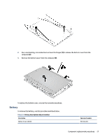
5 Removal and replacement procedures for authorized service provider parts This chapter provides removal and replacement procedures for authorized service provider parts. IMPORTANT: Components described in this chapter should be accessed only by an authorized service provider. Accessing these parts can damage the computer or void the warranty. NOTE: Details about your computer, including model, serial number, product key, and length of warranty, are on the service tag at the bottom of your computer. Component replacement procedures To remove and replace computer components, use these procedures. NOTE: HP continually improves and changes product parts. For complete and current information about supported parts for your computer, go to http://partsurfer.hp.com, select your country or region, and then follow the on-screen instructions. You must remove, replace, or loosen as many as 50 screws when you service the parts described in this chapter. Make special note of each screw size and location during removal and replacement. Preparation for disassembly To remove and replace computer components, use these procedures. See Removal and replacement procedures preliminary requirements on page 18 for initial safety procedures. 1. Turn off the computer. If you are unsure whether the computer is off or in Hibernation, turn the computer on, and then shut it down through the operating system. 2. Disconnect the power from the computer by unplugging the power cord from the computer. 3. Disconnect all external devices from the computer. Bottom cover To remove the bottom cover, use this procedure and illustration. Table 5-1 Bottom cover description and part number Description Spare part number Bottom cover M31754-001 Before removing the bottom cover, prepare the computer for disassembly (see Preparation for disassembly on page 26). Remove the bottom cover: 1. Remove the four Phillips M2.0 × 7.0 screws (1) from the sides and top and the three Phillips M2.0 × 4.0 screws (2) from the bottom that secure the bottom cover to the computer. 26 Chapter 5 Removal and replacement procedures for authorized service provider parts
-
 1
1 -
2
-
3
-
4
-
5
-
6
-
7
-
8
-
9
-
10
-
11
-
12
-
13
-
14
-
15
-
16
-
17
-
18
-
19
-
20
-
21
-
22
-
23
-
24
-
25
-
26
-
27
-
28
-
 29
29 -
 30
30 -
 31
31 -
 32
32 -
 33
33 -
 34
34 -
 35
35 -
 36
36 -
 37
37 -
 38
38 -
 39
39 -
40
-
41
-
42
-
43
-
44
-
45
-
46
-
47
-
48
-
49
-
50
-
51
-
52
-
53
-
54
-
55
-
56
-
57
-
58
-
59
-
60
-
61
-
62
-
63
-
64
-
65
-
66
-
67
-
68
-
69
-
70
-
71
-
72
 |
 |
