HP Pro c640 G2 Chromebook Enterprise Maintenance and Service Guide - Page 37
Solid-state drive, Speakers, Remove the Phillips M2.0 × 3.0 screw
 |
View all HP Pro c640 G2 Chromebook Enterprise manuals
Add to My Manuals
Save this manual to your list of manuals |
Page 37 highlights
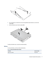
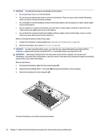
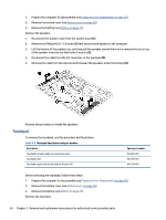
Solid-state drive To remove the M.2 solid-state drive, use this procedure and illustration. Table 5-3 Solid-state drive description and part number Description Solid-state drive, 256 GB Solid-state drive, 128 GB Spare part number M11042-002 M11040-002 Before removing the solid-state drive, follow these steps: 1. Prepare the computer for disassembly (see Preparation for disassembly on page 26). 2. Remove the bottom cover (see Bottom cover on page 26). 3. Remove the battery (see Battery on page 27). Remove the solid-state drive: 1. Remove the Phillips M2.0 × 3.0 screw (1) that secures the drive to the computer. 2. Pull the drive away from the socket to remove it (2). To install the solid-state drive, reverse the removal procedures. NOTE: Solid-state drives are designed with a notch to prevent incorrect insertion. Speakers To remove the speakers, use this procedure and illustration. Table 5-4 Speaker description and part number Description Speaker Kit Spare part number M00436-001 Before removing the speakers, follow these steps: Component replacement procedures 29
-
 1
1 -
2
-
3
-
4
-
5
-
6
-
7
-
8
-
9
-
10
-
11
-
12
-
13
-
14
-
15
-
16
-
17
-
18
-
19
-
20
-
21
-
22
-
23
-
24
-
25
-
26
-
27
-
28
-
29
-
30
-
31
-
 32
32 -
 33
33 -
 34
34 -
 35
35 -
 36
36 -
 37
37 -
 38
38 -
 39
39 -
 40
40 -
 41
41 -
 42
42 -
43
-
44
-
45
-
46
-
47
-
48
-
49
-
50
-
51
-
52
-
53
-
54
-
55
-
56
-
57
-
58
-
59
-
60
-
61
-
62
-
63
-
64
-
65
-
66
-
67
-
68
-
69
-
70
-
71
-
72
 |
 |
