HP Pro c640 G2 Chromebook Enterprise Maintenance and Service Guide - Page 43
Lock bracket, Prepare the computer for disassembly see
 |
View all HP Pro c640 G2 Chromebook Enterprise manuals
Add to My Manuals
Save this manual to your list of manuals |
Page 43 highlights
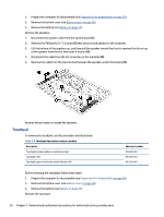
2. Thoroughly clean the thermal material from the surfaces of the heat sink and the system board components each time the heat sink is removed. Replacement thermal material is included with the heat sink and system board spare part kits. The following illustration shows the replacement thermal material locations. Thermal paste is used on one system board component (1) and on the heat sink area (2) that services it. Reverse this procedure to install the heat sink. Lock bracket To remove the lock bracket, use this procedure and illustration. Table 5-9 Lock bracket description and part number Description Lock bracket Spare part number M00433-001 Before removing the lock bracket, follow these steps: 1. Prepare the computer for disassembly (see Preparation for disassembly on page 26). 2. Remove the bottom cover (see Bottom cover on page 26). 3. Remove the battery (see Battery on page 27). Remove the lock bracket: 1. Remove the Phillips M2.0 × 3.0 screw (1) that secures the lock bracket to the computer. Component replacement procedures 35
-
 1
1 -
2
-
3
-
4
-
5
-
6
-
7
-
8
-
9
-
10
-
11
-
12
-
13
-
14
-
15
-
16
-
17
-
18
-
19
-
20
-
21
-
22
-
23
-
24
-
25
-
26
-
27
-
28
-
29
-
30
-
31
-
32
-
33
-
34
-
35
-
36
-
37
-
 38
38 -
 39
39 -
 40
40 -
 41
41 -
 42
42 -
 43
43 -
 44
44 -
 45
45 -
 46
46 -
 47
47 -
 48
48 -
49
-
50
-
51
-
52
-
53
-
54
-
55
-
56
-
57
-
58
-
59
-
60
-
61
-
62
-
63
-
64
-
65
-
66
-
67
-
68
-
69
-
70
-
71
-
72
 |
 |
