HP ProLiant BL35p ProLiant BL35p Server Blade Maintenance and Service Guide - Page 27
System board assembly
 |
View all HP ProLiant BL35p manuals
Add to My Manuals
Save this manual to your list of manuals |
Page 27 highlights
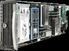
3. Remove the server blade handle. To replace the component: 1. Place the server blade handle over the spring on the server blade. 2. Install the screw to secure the handle and spring. System board assembly The system board assembly consists of the system board, the chassis, the power button/LED board, and the two cables. To remove the component: 1. Power down the server blade (on page 13). 2. Remove the server blade (on page 13). 3. Remove the drive cage assembly ("ATA drive cage assembly" on page 14, "SAS drive cage assembly" on page 15). 4. Remove all DIMMs ("DIMMs" on page 19). 5. Remove the processors ("Processor" on page 20). 6. Remove the fan assembly ("Fan assembly" on page 23). 7. Remove the Dual Port Fibre Channel Adapter, if installed ("Dual Port Fibre Channel Adapter (2 GB)" on page 24). 8. Remove the NIC riser board ("NIC riser board" on page 24). NOTE: Always retain the server blade handle. The handle contains a serial number that maintains the original server blade warranty. 9. Remove the server blade handle ("Server blade handle" on page 26). To replace the component, reinstall all removed subcomponents in the replacement system board assembly. Removal and replacement procedures 27
-
 1
1 -
2
-
3
-
4
-
5
-
6
-
7
-
8
-
9
-
10
-
11
-
12
-
13
-
14
-
15
-
16
-
17
-
18
-
19
-
20
-
21
-
 22
22 -
 23
23 -
 24
24 -
 25
25 -
 26
26 -
 27
27 -
 28
28 -
 29
29 -
 30
30 -
 31
31 -
 32
32 -
33
-
34
-
35
-
36
-
37
-
38
-
39
-
40
-
41
-
42
-
43
-
44
 |
 |
