HP ProLiant BL620c HP BladeSystem c-Class architecture - Page 12
Channel topology and equalization settings, Signal midplane provides reliability, Switch, Device
 |
View all HP ProLiant BL620c manuals
Add to My Manuals
Save this manual to your list of manuals |
Page 12 highlights
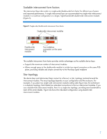
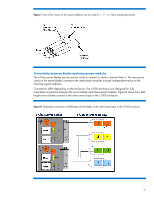
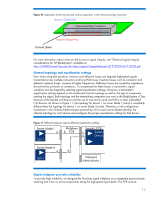
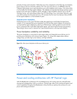
Figure 10. Separation of the transmit and receive signal pins in the interconnect bay connector Receive Signal Pins Interconnect Bay Connector Transmit Signal Pins Ground plane For more information about what we did to ensure signal integrity, see "Electrical signal integrity considerations for HP BladeSystem" available at http://h20000.www2.hp.com/bc/docs/support/SupportManual/c01712559/c01712559.pdf. Channel topology and equalization settings Even when using best practices, insertion and reflection losses can degrade high-speed signals transmitted across multiple connectors and long PCB traces. Insertion losses, such as conductor and dielectric material losses, increase at higher frequencies. Reflection losses are caused by impedance discontinuities, primarily at connectors. To compensate for these losses, a transmitter's signal waveform can be shaped by selecting signal equalization settings. However, a transmitter's equalization settings depend on the end-to-end channel topology as well as the type of component sending the signal. Both topology and the transmitting component can vary in the BladeSystem c-Class because of the flexible architecture and the use of mezzanine cards and NICs or other embedded I/O devices. As shown in Figure 11, the topology for device 1 on server blade 1 (a-b-c) is completely different than the topology for device 1 on server blade 4 (a-d-e). Therefore, a link configuration mechanism in the Onboard Administrator (assisted by iLO on each server blade) identifies the channel topology for each device and configures the proper equalization settings for that device. Figure 11. Different instances require different equalization settings Server blade-1 a DEV-1 Midplane b PCB Switch-1 PCB c Switch e Device Server blade-4 a d DEV-1 Onboard Administrator Signal midplane provides reliability To provide high reliability, we designed the NonStop signal midplane as a completely passive board, meaning that it has no active components along the high-speed signal paths. The PCB consists 12
-
 1
1 -
2
-
3
-
4
-
5
-
6
-
 7
7 -
 8
8 -
 9
9 -
 10
10 -
 11
11 -
 12
12 -
 13
13 -
 14
14 -
 15
15 -
 16
16 -
 17
17 -
18
-
19
-
20
-
21
-
22
-
23
 |
 |
