HP ProLiant BL620c HP BladeSystem c-Class architecture - Page 13
Separate power backplane, Power backplane scalability and reliability
 |
View all HP ProLiant BL620c manuals
Add to My Manuals
Save this manual to your list of manuals |
Page 13 highlights
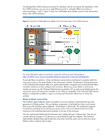
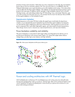
primarily of traces and connectors. While there are a few components on the PCB, they are limited to passive devices that are extremely unlikely to fail. The only active device is an EEPROM which the Onboard Administrator uses to get information such as the midplane serial number. If this device fails, it will not affect the NonStop signal midplane. The midplane incorporates best design practices and is based on the same type of midplane used for decades in high-availability solutions such as the HP NonStop S-series, core networking switches from HP Networking, Cisco, and Juniper Networks, and core SAN switches from Brocade and Cisco. HP estimates that the mean time between failure (MTBF) for the signal midplane is in the hundreds of years. Separate power backplane Distributing power on the same PCB that includes the signal traces would make the board more complex, so we separated the power backplane from the NonStop signal midplane. By doing this, we improved the signal midplane by reducing its PCB thickness, reducing electrical noise from the power components that would affect high-speed signals, and improving the thermal characteristics. These design choices result in reduced cost, improved performance, and improved reliability. Power backplane scalability and reliability The power backplane is constructed of solid copper plates and integrated power delivery pins to provide power distribution with minimum losses (Figure 12). Using solid copper plates reduces voltage drops, provides high current density, and high reliability. Figure 12. c-Class power backplane and the power delivery pins Power and cooling architecture with HP Thermal Logic With the BladeSystem architecture, HP consolidated power and cooling resources while efficiently sharing and managing them within an enclosure. Thermal Logic refers to the mechanical features and control capabilities throughout the BladeSystem c-Class that let you optimize the enclosure for your power and cooling environment. 13
-
 1
1 -
2
-
3
-
4
-
5
-
6
-
7
-
 8
8 -
 9
9 -
 10
10 -
 11
11 -
 12
12 -
 13
13 -
 14
14 -
 15
15 -
 16
16 -
 17
17 -
 18
18 -
19
-
20
-
21
-
22
-
23
 |
 |
