HP R1500 HP UPS R5000 Installation Instructions - Page 8
Connecting the network cable, Connecting the UPS to utility power, Connecting devices to the UPS
 |
View all HP R1500 manuals
Add to My Manuals
Save this manual to your list of manuals |
Page 8 highlights
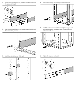
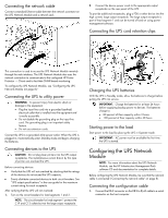
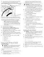
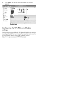
Connecting the network cable Connect a standard Ethernet cable between the network connector on the UPS Network Module and a network jack. 2. Connect the device power cords to the appropriate output receptacles on the rear panel of the UPS. To provide additional receptacles, plug a PDU or other device into the high current, large output receptacle. The large output receptacle is part of load segment 1 and can be turned off and on using power management software. Connecting the UPS cord retention clips This connection is used to access the UPS Network Module remotely through the web interface. The UPS Network Module also uses the network connection to communicate to the configured HP Power Protector - Clients and to facilitate SNMP-based monitoring. To configure the UPS Network Module, see "Configuring the UPS Network Module (on page 8)." Connecting the UPS to utility power WARNING: To prevent injury from electric shock or damage to the equipment: • Plug the input line cord into a grounded (earthed) electrical outlet that is installed near the equipment and is easily accessible. • Do not disable the grounding plug on the input line cord. The grounding plug is an important safety feature. • Do not use extension cords. Connect the UPS to a grounded utility power outlet. When the UPS is plugged in, it automatically enters Standby mode and begins charging the batteries. Connecting devices to the UPS CAUTION: Do not plug laser printers into the UPS output receptacles. The instantaneous current drawn by this type of printer can overload the UPS. Before connecting devices: • Verify that the UPS will not overload by checking that the ratings of the devices do not exceed the UPS capacity. • Evenly distribute connected devices to both circuit breakers. See "UPS output specifications" in the user guide for the maximum current rating for each receptacle. After verifying that the UPS will not overload: 1. Turn on the circuit breakers for load segments 1 and 2. NOTE: The circuit breaker for load segment 1 protects the C19 and C13 outlets but not the large output receptacle. Charging the UPS batteries With the UPS in Standby mode, allow the batteries to charge before putting the UPS into service. IMPORTANT: Charge the batteries for at least 24 hours before supplying backup power to devices. The batteries charge to: • 80 percent of their capacity within 3 hours • 100 percent of their capacity within 48 hours Starting power to the load Start power to the load by placing the UPS in Operate mode. IMPORTANT: AC power must be available the first time the UPS is started. Configuring the UPS Network Module NOTE: For more information about the UPS Network Module, see the HP Infrastructure Management Pack software CD and documentation for complete details. Before configuring the UPS Network Module, be sure that the network cable is connected ("Connecting the network cable" on page 8). Connecting the configuration cable 1. Connect the DB-9 connector on the DB-9 to RJ-45 cable to a serial connector on the host computer.
-
 1
1 -
2
-
 3
3 -
 4
4 -
 5
5 -
 6
6 -
 7
7 -
 8
8 -
 9
9 -
 10
10 -
 11
11
 |
 |
