HP Scitex FB10000 Geffen TS Error 66033 - Page 3
Recommended Actions, Real Overflow event - Drain light cyan main ink tank
 |
View all HP Scitex FB10000 manuals
Add to My Manuals
Save this manual to your list of manuals |
Page 3 highlights
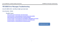
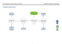
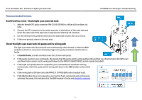
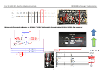
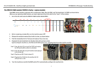
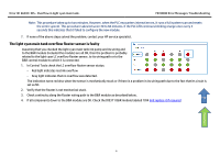
Error ID: 66033: IDS - Overflow in light cyan main tank. FB10000 Error Messages Troubleshooting Recommended Actions Real Overflow event - Drain light cyan main ink tank 1. Attach a female CPC quick connector (PN CX145-06740) to a 40cm x0.8 cm diam. ink tube. 2. Connect the CPC connector to the male connector at the bottom of the main tank and direct the other end of the pipe into an appropriate collecting ink container. 3. Let the ink flow freely until the ink level in the main tank reaches the correct level. 4. If the error persists, move to the next step. Check the light cyan main tank ink pump and its wiring path Top The light cyan main tank ink pump will work continuously when shorted, or when the B&R module to which it is connected constantly triggers the pump activation and therefore is faulty. Flowchart 1. In Control Tools, activate and deactivate the LC main tank pump. 2. If the pump reacts to your commands, this means that the pump and its wiring path are OK and that you should enquire the light cyan overflow floater sensor and its wiring path down to the MM4331 B&R [1MM3] control module (included). 3. If the Light cyan pump does not respond to your commands and continues working continuously, check the pump and its wiring path down to the B&R module as described below. 4. If the wiring path is OK then check the MM4331 [1MM3] B&R control module itself. 5. If the B&R module does not respond to your Control Tools commands and continuously activates the pump, this indicates that the B&R module is faulty and should be replaced. 3
-
 1
1 -
 2
2 -
 3
3 -
 4
4 -
 5
5 -
 6
6 -
 7
7 -
 8
8 -
 9
9
 |
 |
