HP Scitex FB10000 Geffen TS Error 67009 - Page 3
Recommended Actions
 |
View all HP Scitex FB10000 manuals
Add to My Manuals
Save this manual to your list of manuals |
Page 3 highlights
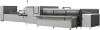
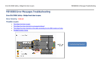
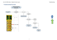
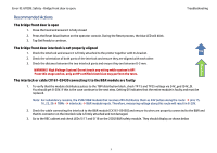
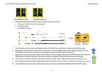
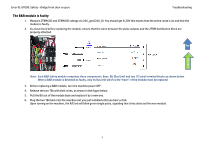
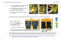
Error ID: 67009: Safety - Bridge front door is open. Troubleshooting Flowchart Recommended Actions The bridge front door is open 1. Close the hood and ensure it is fully closed 2. Press the Reset (blue) button on the operator console. During the Reset process, the blue LED will blink. 3. Tap Get Ready to continue. The bridge front door interlock is not properly aligned Top 1. Check the interlock and ensure it is firmly attached to the printer together with its bracket. 2. Check the orientation of both parts of the interlock and ensure they are aligned with each other. 3. Check the distance between the two interlock parts and ensure they are between 0-3 mm. WARNING! High Voltage System! Do not touch any wiring while system is UP! From this stage and on, only an HP certified electrician may perform the tests. The interlock or cable CX161-03430 connecting it to the B&R module are faulty 1. To verify that the module distributes pulses to the TBM distribution block, check TP 15 and TP25 voltage via 24V_gnd (24V_0). You should get 8-20V. If this is the case continue to the next step. Getting 0V indicates that the entire module is faulty and must be replaced. Note: For redundancy reasons, the 2SDI2 B&R module that receives 24V distributes them as 24V pulses along the route: pins 15, 16, 25, 26 TBMs interlocks B&R module inputs. Therefore, measuring voltage along this route will result in 8-20V. 2. Check the cable connecting the interlock to the B&R module [CX161-03430] and ensure its wires are properly connected to the B&R and that its connector on the interlock side is firmly attached and not damaged. 3. Go to the REC cabinet and check LEDs SI 17 and SI 18 on the 2SDI2 B&R safety module. They should display as shown below 3
-
 1
1 -
 2
2 -
 3
3 -
 4
4 -
 5
5 -
 6
6 -
 7
7 -
 8
8
 |
 |
