HP Special Edition L2005CM HP Special Edition L2000 Notebook PC and Compaq Pre - Page 105
Remove the four PM2.0×6.0 screws, that secure the display
 |
View all HP Special Edition L2005CM manuals
Add to My Manuals
Save this manual to your list of manuals |
Page 105 highlights
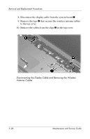
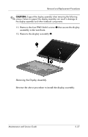
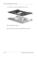
Removal and Replacement Procedures ✎ CAUTION: Support the display assembly when removing the following screws. Failure to support the display assembly can result in damage to the display assembly and other notebook components. 11. Remove the four PM2.0×6.0 screws 1 that secure the display assembly to the notebook. 12. Remove the display assembly 2. Removing the Display Assembly Reverse the above procedure to install the display assembly Maintenance and Service Guide 5-27
-
 1
1 -
2
-
3
-
4
-
5
-
6
-
7
-
8
-
9
-
10
-
11
-
12
-
13
-
14
-
15
-
16
-
17
-
18
-
19
-
20
-
21
-
22
-
23
-
24
-
25
-
26
-
27
-
28
-
29
-
30
-
31
-
32
-
33
-
34
-
35
-
36
-
37
-
38
-
39
-
40
-
41
-
42
-
43
-
44
-
45
-
46
-
47
-
48
-
49
-
50
-
51
-
52
-
53
-
54
-
55
-
56
-
57
-
58
-
59
-
60
-
61
-
62
-
63
-
64
-
65
-
66
-
67
-
68
-
69
-
70
-
71
-
72
-
73
-
74
-
75
-
76
-
77
-
78
-
79
-
80
-
81
-
82
-
83
-
84
-
85
-
86
-
87
-
88
-
89
-
90
-
91
-
92
-
93
-
94
-
95
-
96
-
97
-
98
-
99
-
 100
100 -
 101
101 -
 102
102 -
 103
103 -
 104
104 -
 105
105 -
 106
106 -
 107
107 -
 108
108 -
 109
109 -
 110
110 -
111
-
112
-
113
-
114
-
115
-
116
-
117
-
118
-
119
-
120
-
121
-
122
-
123
-
124
-
125
-
126
-
127
-
128
-
129
-
130
-
131
-
132
-
133
-
134
-
135
-
136
-
137
-
138
-
139
-
140
-
141
-
142
-
143
-
144
-
145
-
146
-
147
-
148
-
149
-
150
-
151
-
152
-
153
-
154
-
155
-
156
-
157
-
158
-
159
-
160
-
161
-
162
-
163
-
164
-
165
-
166
-
167
-
168
-
169
-
170
-
171
-
172
-
173
-
174
-
175
-
176
 |
 |

Removal and Replacement Procedures
Maintenance and Service Guide
5–27
✎
CAUTION:
Support the display assembly when removing the following
screws. Failure to support the display assembly can result in damage to
the display assembly and other notebook components.
11.
Remove the four PM2.0×6.0 screws
1
that secure the display
assembly to the notebook.
12. Remove the display assembly
2
.
Removing the Display Assembly
Reverse the above procedure to install the display assembly