HP Special Edition L2005CM HP Special Edition L2000 Notebook PC and Compaq Pre - Page 117
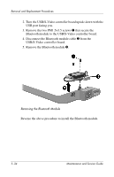
that secure the fan assembly to the system board., Remove the fan assembly
 |
View all HP Special Edition L2005CM manuals
Add to My Manuals
Save this manual to your list of manuals |
Page 117 highlights
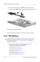
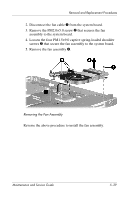
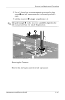
Removal and Replacement Procedures 2. Disconnect the fan cable 1 from the system board. 3. Remove the PM2.0×5.0 screw 2 that secures the fan assembly to the system board. 4. Loosen the four PM1.5×9.0 captive spring-loaded shoulder screws 3 that secure the fan assembly to the system board. 5. Remove the fan assembly 4. Removing the Fan Assembly Reverse the above procedure to install the fan assembly. Maintenance and Service Guide 5-39
-
 1
1 -
2
-
3
-
4
-
5
-
6
-
7
-
8
-
9
-
10
-
11
-
12
-
13
-
14
-
15
-
16
-
17
-
18
-
19
-
20
-
21
-
22
-
23
-
24
-
25
-
26
-
27
-
28
-
29
-
30
-
31
-
32
-
33
-
34
-
35
-
36
-
37
-
38
-
39
-
40
-
41
-
42
-
43
-
44
-
45
-
46
-
47
-
48
-
49
-
50
-
51
-
52
-
53
-
54
-
55
-
56
-
57
-
58
-
59
-
60
-
61
-
62
-
63
-
64
-
65
-
66
-
67
-
68
-
69
-
70
-
71
-
72
-
73
-
74
-
75
-
76
-
77
-
78
-
79
-
80
-
81
-
82
-
83
-
84
-
85
-
86
-
87
-
88
-
89
-
90
-
91
-
92
-
93
-
94
-
95
-
96
-
97
-
98
-
99
-
100
-
101
-
102
-
103
-
104
-
105
-
106
-
107
-
108
-
109
-
110
-
111
-
 112
112 -
 113
113 -
 114
114 -
 115
115 -
 116
116 -
 117
117 -
 118
118 -
 119
119 -
 120
120 -
 121
121 -
 122
122 -
123
-
124
-
125
-
126
-
127
-
128
-
129
-
130
-
131
-
132
-
133
-
134
-
135
-
136
-
137
-
138
-
139
-
140
-
141
-
142
-
143
-
144
-
145
-
146
-
147
-
148
-
149
-
150
-
151
-
152
-
153
-
154
-
155
-
156
-
157
-
158
-
159
-
160
-
161
-
162
-
163
-
164
-
165
-
166
-
167
-
168
-
169
-
170
-
171
-
172
-
173
-
174
-
175
-
176
 |
 |

Removal and Replacement Procedures
Maintenance and Service Guide
5–39
2. Disconnect the fan cable
1
from the system board.
3. Remove the PM2.0×5.0 screw
2
that secures the fan
assembly to the system board.
4. Loosen the four PM1.5×9.0 captive spring-loaded shoulder
screws
3
that secure the fan assembly to the system board.
5. Remove the fan assembly
4
.
Removing the Fan Assembly
Reverse the above procedure to install the fan assembly.