| Section |
Page |
| <TABLE> |
11 |
| <TABLE> |
12 |
| 1 System Overview |
13 |
| Workstation Description |
14 |
| <TABLE> |
14 |
| Packaging |
16 |
| Figure�1�1 Workstation |
16 |
| Figure�1�2 Location of Rear Panel Connectors |
16 |
| Internal Features |
17 |
| <TABLE> |
17 |
| Front Panel |
18 |
| Figure�1�3 Front Panel |
18 |
| Specifications And Characteristics |
19 |
| Physical Characteristics |
19 |
| <TABLE> |
19 |
| Electrical Specifications |
19 |
| <TABLE> |
19 |
| Power Consumption And Cooling |
20 |
| <TABLE> |
20 |
| Environmental Specifications |
21 |
| <TABLE> |
21 |
| Power Saving And Ergonometry |
21 |
| <TABLE> |
21 |
| Power Saving And Ergonometry For APM Systems |
22 |
| <TABLE> |
22 |
| Power Saving Modes/Resume Events For ACPI Systems |
22 |
| <TABLE> |
22 |
| Soft Power Down |
23 |
| Documentation |
23 |
| Access HP World Wide Web Site |
23 |
| Where To Find The Information |
23 |
| 2 System Board |
25 |
| System Board Description |
26 |
| Figure�2�1 System Board Dimensions |
26 |
| Figure�2�2 System Board Chips and Connectors |
27 |
| Architectural View For The x1100 Workstation |
28 |
| Accessory Board Slots |
29 |
| Figure�2�3 Accessory Board Slots |
29 |
| Accelerated Graphics Port Slot |
29 |
| Figure�2�4 AGP Slot |
29 |
| Peripheral Component Interconnect Slots |
30 |
| Figure�2�5 PCI Slots |
30 |
| <TABLE> |
30 |
| System Board Switches |
32 |
| Figure�2�6 System Board Switches |
32 |
| <TABLE> |
32 |
| Chipset |
33 |
| Memory Controller Hub (82845) |
34 |
| Figure�2�7 MCH Chip Location |
34 |
| Figure�2�8 System Block Diagram using MCH |
34 |
| <TABLE> |
35 |
| MCH Overview |
37 |
| Accelerated Graphics Port (AGP) Bus Interface |
37 |
| hub interface |
37 |
| DDR SDRAM Interface |
38 |
| DIMM Memory Slots |
38 |
| Figure�2�9 DIMM Memory Slot |
38 |
| Read/Write Buffers |
39 |
| System Clocking |
39 |
| Input/output Controller Hub 2 (82801BA) |
40 |
| Figure�2�10 Input/Output Controller Hub 2 Chip |
40 |
| Figure�2�11 System Block Diagram Using ICH2 |
41 |
| <TABLE> |
41 |
| ICH2 Features |
43 |
| ICH2 Architecture |
43 |
| ICH2 PCI Bus Interface |
43 |
| SMBus Controller |
43 |
| Low Pin Count Interface |
43 |
| Enhanced USB Controller |
43 |
| AC’97 Controller |
44 |
| IDE Controller |
44 |
| DMA Controller |
44 |
| Interrupt Controller |
45 |
| Timer/Counter Block |
45 |
| Advanced Programmable Interrupt Controller |
45 |
| Real Time Clock |
45 |
| Enhanced Power Management |
46 |
| SoundMAX® Codec (AD1885) |
46 |
| SMBus |
47 |
| Figure�2�12 Devices on the SMBus |
47 |
| ICH2 SMBus Master Controller |
47 |
| Devices On The LPC Bus |
48 |
| Figure�2�13 Devices on the LPC Bus |
48 |
| The Super I/O Controller |
48 |
| Serial/Parallel Communications Ports |
48 |
| FDC |
49 |
| Keyboard And Mouse Controller |
49 |
| FirmWare Hub (82802AB) |
50 |
| <TABLE> |
50 |
| System Bus |
52 |
| Figure�2�14 The System Bus |
52 |
| Intel Pentium 4 processor |
52 |
| Processor Clock |
53 |
| Bus Frequencies |
53 |
| Voltage Regulation Module (VRM) |
53 |
| Cache Memory |
53 |
| Assigned Device Interrupts |
54 |
| I/O Controller Hub Interrupts |
54 |
| <TABLE> |
54 |
| Interrupt Controllers |
54 |
| PCI IRQ Lines |
55 |
| 3 HP BIOS |
57 |
| Overview |
58 |
| Using The HP Setup Program |
58 |
| Main Screen |
59 |
| <TABLE> |
59 |
| Advanced Screen |
59 |
| <TABLE> |
59 |
| Processors, Memory And Cache |
59 |
| <TABLE> |
59 |
| Floppy Options |
60 |
| <TABLE> |
60 |
| IDE Device Configuration |
60 |
| <TABLE> |
60 |
| IDE Primary Master Device |
60 |
| <TABLE> |
60 |
| Integrated USB Interface |
60 |
| <TABLE> |
60 |
| Peripheral Configuration |
61 |
| <TABLE> |
61 |
| Integrated Audio Device |
61 |
| <TABLE> |
61 |
| Integrated LAN |
61 |
| <TABLE> |
61 |
| Video Configuration |
61 |
| <TABLE> |
61 |
| PCI Device, Slot #1 |
61 |
| <TABLE> |
61 |
| Security Screen |
62 |
| <TABLE> |
62 |
| Device Start Protection |
62 |
| <TABLE> |
62 |
| Hardware Protection |
62 |
| <TABLE> |
62 |
| Boot Screen |
62 |
| <TABLE> |
63 |
| Power Screen |
63 |
| <TABLE> |
63 |
| Exit Screen |
63 |
| <TABLE> |
63 |
| Updating The System BIOS |
64 |
| Figure�3�1 System BIOS Flash Process |
64 |
| Restoring BIOS Default Settings |
64 |
| If You Forgot The Administrator Password |
64 |
| Clearing The CMOS |
65 |
| Recovering The BIOS (crisis mode) |
65 |
| BIOS Addresses |
66 |
| System Memory Map |
66 |
| HP I/O Port Map (I/O addresses used by the system, if configured) |
66 |
| <TABLE> |
66 |
| DMA Channel Controllers |
67 |
| <TABLE> |
67 |
| Interrupt Controllers |
68 |
| <TABLE> |
68 |
| PCI IRQ Lines |
69 |
| 4 Pre-boot Diagnostics And BIOS Errors |
71 |
| HP e-Diagtools |
72 |
| Overview Of e-Diagtools |
72 |
| Pre-boot Audio Signal And Beeps |
73 |
| <TABLE> |
73 |
| BIOS Error Messages |
74 |
| Handling Pre-boot, BIOS, or e-Diagtools Errors |
74 |
| Calling Your Support Provider |
74 |
| Troubleshooting The Error Yourself |
75 |
| e-Diagtools Online Troubleshooting |
76 |
| Running e-Diagtools |
77 |
| Running e-Diagtools From The Utility Partition On Your Hard Disk |
77 |
| Running e-Diagtools From A CD-ROM |
78 |
| prerequisites |
78 |
| Running e-Diagtools From The HP Recovery CD |
78 |
| Running e-Diagtools From The HP Diagtools CD-ROM |
78 |
| HP e-Diagtools Hardware Tests |
79 |
| For More Information |
79 |
| 5 Hardware Components |
81 |
| Selecting A Monitor For Your Workstation |
82 |
| <TABLE> |
82 |
| Graphics Cards |
83 |
| Matrox Millennium G450 Graphics Card |
83 |
| 3D Features |
83 |
| Figure�5�1 Matrox Millennium G450 Graphics Card |
84 |
| available video resolutions |
84 |
| <TABLE> |
85 |
| LIMITATIONS |
85 |
| nVIDIA Quadro2 Pro |
85 |
| Figure�5�2 nVIDIA Quadro2 Pro Graphics Card |
86 |
| nVIDIA Quadro2 EX |
86 |
| Figure�5�3 nVIDIA Quadro2 EX Graphics Card |
86 |
| 3D features |
86 |
| SCSI Adapter Cards |
88 |
| Adaptec 29160 SCSI PCI adapter card |
88 |
| Figure�5�4 Adaptec SCSI Card |
88 |
| External SCSI Cable Information |
89 |
| Additional SCSI Card Features |
89 |
| <TABLE> |
89 |
| IEEE-1394 (Firewire) Card |
90 |
| Figure�5�5 IEEE-1394 (Firewire) Card |
90 |
| IEEE-1394 Cable |
90 |
| Figure�5�6 Cross Section of the IEEE-1394 Cable |
90 |
| Mass Storage Devices |
92 |
| Flexible Disk Drives |
92 |
| Hard Disk Drives |
92 |
| <TABLE> |
92 |
| <TABLE> |
92 |
| CD-ROM Drives |
93 |
| IDE 48X CD-ROM Drive |
93 |
| <TABLE> |
93 |
| CD-RW Drive |
93 |
| <TABLE> |
93 |
| DVD-ROM Drive |
94 |
| <TABLE> |
94 |
| DVD+RW Drive |
94 |
| <TABLE> |
94 |
| Connectors And Sockets |
96 |
| IDE Drive Connectors |
96 |
| <TABLE> |
96 |
| Battery Pinouts |
96 |
| <TABLE> |
96 |
| Additional SCSI LED Connector |
96 |
| <TABLE> |
96 |
| Power Supply Connector (20-pin) and Aux Power Connector |
96 |
| <TABLE> |
97 |
| Wake On LAN Connector |
98 |
| <TABLE> |
98 |
| System Fan Connector |
98 |
| <TABLE> |
98 |
| Internal Audio Connectors |
98 |
| <TABLE> |
98 |
| Intrusion |
98 |
| <TABLE> |
98 |
| AGP Connector |
98 |
| <TABLE> |
98 |
| IEEE-1394 Connectors |
100 |
| <TABLE> |
100 |
| Ethernet Connector |
100 |
| Figure�5�7 Ethernet UTP Connector |
100 |
| Rear Panel |
101 |
| Figure�5�8 Rear Panel Socket Pin Layouts |
101 |
| Keyboard And Mouse Connectors |
102 |
| <TABLE> |
102 |
| USB Stacked Connector |
102 |
| <TABLE> |
102 |
| Serial Port Connectors |
103 |
| <TABLE> |
103 |
| 25-pin Parallel Connector |
104 |
| <TABLE> |
104 |
| External Audio Jacks |
104 |
| 6 Removing And Replacing Hardware Parts |
105 |
| Overview |
106 |
| Figure�6�1 Workstation |
106 |
| Figure�6�2 System Board Connectors and Slots |
107 |
| Removing And Replacing The Cover And Front�Bezel |
108 |
| Removing The Workstation’s Cover |
108 |
| Removing The Front Bezel |
108 |
| Figure�6�4 Removing the Bezel |
109 |
| Replacing The Cover And Front Bezel |
109 |
| Figure�6�5 Inserting the Bezel Hinges into their Slots on the Workstation |
109 |
| Figure�6�6 Replacing the Cover |
110 |
| Removing, Replacing And Upgrading Memory |
111 |
| Figure�6�7 System Board Connectors and Slots |
111 |
| Removing And Replacing A Memory Module |
111 |
| Figure�6�8 Removing a Memory Module |
112 |
| Removing Or Replacing An Accessory Card |
113 |
| Removing An AGP Accessory Card |
113 |
| Figure�6�9 Retainer Clip for the Accessory Cards |
113 |
| Figure�6�10 AGP Slot and Retainer Latches |
114 |
| Figure�6�11 Removing the AGP Accessory Card |
115 |
| Replacing An AGP Accessory Card |
115 |
| Removing A SCSI Card |
115 |
| Figure�6�12 Removing the SCSI Cable and SCSI Status Light Cable |
116 |
| Figure�6�13 Removing the SCSI Card |
116 |
| replacing a SCSI card |
116 |
| installing the external 68-pin SCSI connector and cable |
117 |
| SCSI connector considerations |
117 |
| Figure�6�14 SCSI Connectors Viewed from the Back of the Workstation |
117 |
| cables used to connect your external SCSI devices |
118 |
| Figure�6�15 Supported SCSI Cables |
118 |
| installing the SCSI connector |
118 |
| Figure�6�16 Removing the Bulkhead Blank |
118 |
| Figure�6�17 Install the SCSI Connector Bulkhead |
119 |
| Figure�6�18 Connecting the SCSI Connector Cable to the SCSI Card |
119 |
| Removing And Replacing A Hard Disk Drive |
120 |
| Removing A Hard Disk Drive |
120 |
| Figure�6�19 Disconnecting the Power and Data Cables |
120 |
| Figure�6�20 Releasing the Retainer Clips and the Hard Disk Drive |
121 |
| Figure�6�21 Removing the Hard Disk Drive from Its Bracket Guides |
121 |
| Replacing A Hard Disk Drive |
121 |
| Removing And Replacing An Optical Drives |
123 |
| Removing An Optical Drive |
123 |
| Figure�6�22 Disconnecting the Optical Drive’s Power and Data Cables |
123 |
| Figure�6�23 Removing an Optical Drive |
124 |
| Figure�6�24 Removing Optical Drive from its Mounting Bracket |
124 |
| Figure�6�25 Installing the Optical Drive’s Mounting Bracket Filler |
125 |
| Replacing An Optical Drive |
125 |
| Removing And Replacing A Flexible Disk Drive |
126 |
| Removing A Flexible Disk Drive |
126 |
| Figure�6�26 Disconnecting a Flexible Disk Drive’s Power and Data Cables |
126 |
| Figure�6�27 Removing the Flexible Disk Drive |
127 |
| Figure�6�28 Removing the Flexible Drive from Its Mounting Bracket |
127 |
| Replacing A Flexible Disk Drive |
127 |
| Removing And Replacing A Power Supply Unit |
129 |
| Removing A Power Supply Unit |
129 |
| Figure�6�29 Disconnecting Power Supply Cables |
129 |
| Figure�6�30 Unscrew the Power Supply’s Internal Mounting Screw |
130 |
| Figure�6�31 Unscrewing the Power Supply’s Four Mounting Screws |
130 |
| Figure�6�32 Removing the Power Supply |
131 |
| Replacing A Power Supply |
131 |
| Removing And Replacing The Processor |
132 |
| Removing The Existing Processor |
132 |
| Figure�6�33 Disconnecting the Heatsink Fan’s Power Cable |
132 |
| Figure�6�34 Removing the Heatsink and Fan |
133 |
| Figure�6�35 Removing the Processor |
133 |
| Replacing A Processor |
134 |
| Figure�6�36 Replacing the Thermal Bonding Material |
134 |
| Removing And Replacing A System Board |
135 |
| Removing A System Board |
135 |
| Figure�6�37 Unscrewing the System Board Mounting Screws |
135 |
| Figure�6�38 Remove the System Board |
136 |
| Replacing A System Board |
136 |
| Setting System Board Switches |
138 |
| Removing And Replacing A System Speaker |
139 |
| Removing A System Speaker |
139 |
| Figure�6�40 Removing Audio Cable from the System Board |
139 |
| Figure�6�41 Removing a System Speaker |
140 |
| Replacing A System Speaker |
140 |
| Removing And Replacing A System Fan |
141 |
| Removing The System Fan |
141 |
| Figure�6�42 Disconnecting the System Fan Power Cable |
141 |
| Figure�6�43 Removing the System Fan Rivets |
142 |
| Figure�6�44 Removing the System Fan |
142 |
| Replacing A System Fan |
142 |
| Removing And Replacing The System Battery |
144 |
| Removing The System Battery |
144 |
| Figure�6�45 Removing the Battery |
145 |
| Replacing The System Battery |
145 |
| 7 Troubleshooting Your Workstation |
147 |
| Screen Is Blank Because The System Failed To Boot |
148 |
| Figure�7�1 Setting the Workstation’s Line Voltage Switch |
148 |
| Screen Goes Blank Or Corrupt Image |
149 |
| <TABLE> |
149 |
| Troubleshooting BIOS Problems |
150 |
| Updating The BIOS |
150 |
| Restoring BIOS Default Settings |
150 |
| Clearing The CMOS |
150 |
| Recovering The BIOS (crisis mode) |
151 |
| system board switches |
152 |
| Figure�7�2 System Board Switches |
152 |
| Using The HP Setup Program |
153 |
| First, Turn On Or Restart Your Workstation |
153 |
| To Go To The Setup Program |
153 |
| More Troubleshooting For Drives |
154 |
| If The Hard Disk Has A Problem |
154 |
| If The Hard Disk Activity Light Does Not Work |
154 |
| CD-ROM, DVD or CD-RW Drive Does Not Work |
154 |
| CD-ROM, DVD or CD-RW Drive Is Idle |
155 |
| DVD Drive Doesn’t Play DVD Video |
155 |
| CD-ROM, DVD or CD-RW Door Does Not Open |
155 |
| Recovering Hard Disk Drive Contents (Windows only) |
156 |
| Overview |
156 |
| What Functions Are Available? |
156 |
| General Instructions |
156 |
| Recovery Process |
156 |
| Recovering Preloaded Drivers |
157 |
| Changing The Hard Disk |
157 |
| Other Sources Of Information |
158 |
| Online Support For Troubleshooting |
158 |
| Documentation Set Overview |
158 |
| Hewlett-Packard Support And Information Services |
159 |
| Collecting Information Before Contacting HP Support |
159 |
| <TABLE> |
159 |
| A x1100 Service Information |
161 |
| HP x1100 Accessories |
162 |
| x1100 Supported Accessories |
162 |
| <TABLE> |
162 |
| <TABLE> |
162 |
| <TABLE> |
162 |
| <TABLE> |
162 |
| <TABLE> |
163 |
| <TABLE> |
163 |
| <TABLE> |
163 |
| Exploded View And Part Numbers |
164 |
| Figure�A�1 Exploded View of the HP Workstation x1100 Parts |
164 |
 1
1 132
132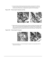 133
133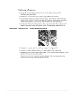 134
134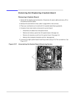 135
135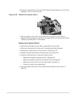 136
136 137
137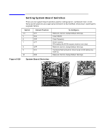 138
138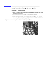 139
139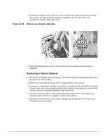 140
140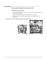 141
141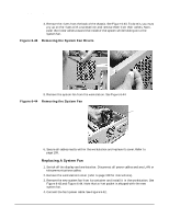 142
142