HP d640 HP D640 High-Volume Printer - 3000-Sheet HCO Installation and User Man - Page 23
Connecting cables and powering up
 |
View all HP d640 manuals
Add to My Manuals
Save this manual to your list of manuals |
Page 23 highlights
Step 2 Push the HCO against the printer as shown in Figure 21. The two metal pins on the back of the HCO are connected to the corresponding holes in the joining frame and the printer latch is engaged. Latch lever Metal pin Note Figure 21 Connecting the HCO To disconnect the HCO from the printer, pull the latch lever towards you and move the HCO away from the printer. Connecting cables and powering up After the HCO and printer are attached, you're ready to connect the interface cable and power cable. Step 1 Plug the interface cable from the HCO into the connector on the back of the printer. See Figure 22. The connector is located at the back of the printer near the bottom. Chapter 1: Introduction 19
-
 1
1 -
2
-
3
-
4
-
5
-
6
-
7
-
8
-
9
-
10
-
11
-
12
-
13
-
14
-
15
-
16
-
17
-
 18
18 -
 19
19 -
 20
20 -
 21
21 -
 22
22 -
 23
23 -
 24
24 -
 25
25 -
 26
26 -
 27
27 -
 28
28 -
29
-
30
-
31
-
32
-
33
-
34
-
35
-
36
-
37
-
38
-
39
-
40
-
41
-
42
-
43
-
44
 |
 |

Chapter 1: Introduction
19
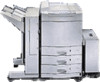
Step 2
Push the HCO against the printer as shown in Figure 21.
The two metal pins on the back of the HCO are connected to the
corresponding holes in the joining frame and the printer latch is
engaged.
Figure 21
Connecting the HCO
Note
To disconnect the HCO from the printer, pull the latch lever towards
you and move the HCO away from the printer.
Connecting cables and powering up
After the HCO and printer are attached, you’re ready to connect the
interface cable and power cable.
Step 1
Plug the interface cable from the HCO into the connector on
the back of the printer. See Figure 22.
The connector is located at the back of the printer near the bottom.
Latch lever
Metal pin