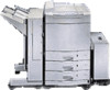
HP d640 HP D640 High-Volume Printer - 3000-Sheet HCO Installation and User Man - Page 41
Index
 |
View all HP d640 manuals
Add to My Manuals
Save this manual to your list of manuals |
Page 41 highlights
Index A A3/A4 paper settings 8 See also paper sizes accessories checking 4 unpacking 2 adjusting paper guides 25-26 paper stopper 24 aligning paper output guide 13 alignment holes, for paper sizes 8 assembling, HCO 6-9 attaching joining frame 17 paper guides 8 paper output guide 13 stopper 6 stopper guide 16 tray 7 Australia EMC certification 35 B buttons Menu 21 Save 22 C certification, Australia EMC 35 checking, accessories 4 clearing, paper jams 26-29 configuring printer for HCO 21- 22 connecting HCO to printer 18-20 interface cable 19 power cable 20 connecting pin, on stopper guide 18 control panel 21, 29, 30 Cover open message 30 D Declaration of Conformity 36 diagnostics, power-up 20, 31 dimensions, of HCO 34 disconnecting, HCO from printer 19 E error messages 30 F flange, on paper guide 8 front door, of printer 26 G grounded outlet 20 H HCO connecting to printer 18-20 error messages 30 knobs and levers 27 powering up 20 printing without 30 separating from printer 19, 28-29 specifications 33-34 unpacking 2-3 using 23-31 HCO door 3, 27 HCO icon, on control panel 21 HCO input area 27 HCO, assembling 6-9 HCO-FACEDOWN setting 22 HCO-FACEUP setting 22 heat production 34 high capacity output. See HCO HP Declaration of Conformity 36 humidity specifications 34 I indicator, paper path 22 inserting, spacer bolts 11, 12, 14 installing. See attaching interface cable 4, 30 connecting 19 interface connector 20 See also interface cable J Jam messages 30 jams. See paper jams joining frame 4 attaching 17 K knobs and levers, inside HCO 27, 28 knurled screws 4, 9, 25 L latch lever. See printer latch levers and knobs, inside HCO 27 M markers, paper size 8, 24, 25 Menu button 21 menus, Printing 21 N Not ready message 31 O outbin setting 21 output tray, using HCO as 22 Index 37
-
 1
1 -
2
-
3
-
4
-
5
-
6
-
7
-
8
-
9
-
10
-
11
-
12
-
13
-
14
-
15
-
16
-
17
-
18
-
19
-
20
-
21
-
22
-
23
-
24
-
25
-
26
-
27
-
28
-
29
-
30
-
31
-
32
-
33
-
34
-
35
-
 36
36 -
 37
37 -
 38
38 -
 39
39 -
 40
40 -
 41
41 -
 42
42 -
 43
43 -
 44
44
 |
 |
