HP rp7440 Site Preparation Guide, Fourth Edition - HP Integrity rx7640 and HP - Page 17
Front Panel, Front Panel Indicators and Controls, Enclosure Status LEDs
 |
View all HP rp7440 manuals
Add to My Manuals
Save this manual to your list of manuals |
Page 17 highlights
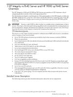
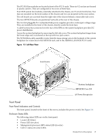
The PCI OLR fan modules are located in front of the PCI-X cards. These six 9.2-cm fans are housed in plastic carriers. They are configured in two rows of three fans. Four OLR system fan modules, externally attached to the chassis, are 15-cm (6.5-inch) fans. Two fans are mounted on the front surface of the chassis and two are mounted on the rear surface. The cell boards are accessed from the right side of the chassis behind a removable side cover. The two MP/SCSI boards are positioned vertically at the rear of the chassis. The two hot-pluggable N+1 redundant bulk power supplies provide a wide input voltage range. They are installed in the front of the chassis, directly under the front fans. A cable harness that connects from the rear of the BPSs to the system backplane provides DC power distribution. Access the system backplane by removing the left side cover. The system backplane hinges from the lower edge and is anchored at the top with two jack screws. The SCSI ribbon-cable assembly routes from the mass storage area to the backside of the system backplane for connection to the MP/SCSI card, and to the AB290A LAN/SCSI PCI-X cards. Figure 1-5 Left-Rear View Jack Screws System backplane MP/SCSI Core I/O AC Power Receptacles Front Panel Front Panel Indicators and Controls The front panel, located on the front of the server, includes the power switch. See Figure 1-6 Enclosure Status LEDs The following status LEDs are on the front panel: • Locate LED (blue) • Power LED (tri-color) • Management processor (MP) status LED (tri-color) • Cell 0, 1 status (tri-color) LEDs Detailed Server Description 17
-
 1
1 -
2
-
3
-
4
-
5
-
6
-
7
-
8
-
9
-
10
-
11
-
 12
12 -
 13
13 -
 14
14 -
 15
15 -
 16
16 -
 17
17 -
 18
18 -
 19
19 -
 20
20 -
 21
21 -
 22
22 -
23
-
24
-
25
-
26
-
27
-
28
-
29
-
30
-
31
-
32
-
33
-
34
-
35
-
36
-
37
-
38
-
39
-
40
-
41
 |
 |
