Hitachi 7K250 Specifications - Page 6

Electrical interface specification

Page 6 highlights

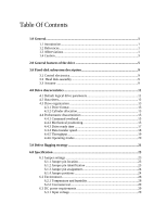
6.3.2 Power supply current (typical 29 6.3.3 Power supply generated ripple at drive power connector 31 6.4 Reliability 32 6.4.1 Data integrity 32 6.4.2 Cable noise interference 32 6.4.3 Start/stop cycles 32 6.4.4 Preventive maintenance 32 6.4.5 Data reliability 32 6.4.6 Required power-off sequence 32 6.5 Mechanical specifications 33 6.5.1 Physical dimensions and weight 33 6.5.2 Mounting hole locations 34 6.5.3 Connector locations 35 6.5.4 Drive mounting 35 6.5.5 Heads unload and actuator lock 35 6.6 Vibration and shock 36 6.6.1 Operating vibration 36 6.6.2 Nonoperating vibration 36 6.6.3 Operating shock 37 6.6.4 Nonoperating shock 37 6.6.5 Nonoperating rotational shock 38 6.7 Acoustics 39 6.8 Identification labels 39 6.9 Safety ...40 6.9.1 UL and CSA approval 40 6.9.2 German safety mark 40 6.9.3 Flammability 40 6.9.4 Safe handling 40 6.9.5 Environment 40 6.9.6 Secondary circuit protection 40 6.10 Electromagnetic compatibility 41 6.10.1 CE mark 41 6.10.2 C-TICK mark 41 6.10.3 BSMI mark 41 6.11 Packaging 41 7.0 Electrical interface specification 43 7.1 Connector location 43 7.1.1 DC power connector 43 7.1.2 AT signal connector 43 7.2 Signal definitions 44 7.3 Signal descriptions 45 7.4 Interface logic signal levels 48 7.5 Reset timings 48 7.6 PIO timings 49 7.6.1 Write DRQ interval time 49

  • 1
  • 2
  • 3
  • 4
  • 5
  • 6
  • 7
  • 8
  • 9
  • 10
  • 11
  • 12
  • 13
  • 14
  • 15
  • 16
  • 17
  • 18
  • 19
  • 20
  • 21
  • 22
  • 23
  • 24
  • 25
  • 26
  • 27
  • 28
  • 29
  • 30
  • 31
  • 32
  • 33
  • 34
  • 35
  • 36
  • 37
  • 38
  • 39
  • 40
  • 41
  • 42
  • 43
  • 44
  • 45
  • 46
  • 47
  • 48
  • 49
  • 50
  • 51
  • 52
  • 53
  • 54
  • 55
  • 56
  • 57
  • 58
  • 59
  • 60
  • 61
  • 62
  • 63
  • 64
  • 65
  • 66
  • 67
  • 68
  • 69
  • 70
  • 71
  • 72
  • 73
  • 74
  • 75
  • 76
  • 77
  • 78
  • 79
  • 80
  • 81
  • 82
  • 83
  • 84
  • 85
  • 86
  • 87
  • 88
  • 89
  • 90
  • 91
  • 92
  • 93
  • 94
  • 95
  • 96
  • 97
  • 98
  • 99
  • 100
  • 101
  • 102
  • 103
  • 104
  • 105
  • 106
  • 107
  • 108
  • 109
  • 110
  • 111
  • 112
  • 113
  • 114
  • 115
  • 116
  • 117
  • 118
  • 119
  • 120
  • 121
  • 122
  • 123
  • 124
  • 125
  • 126
  • 127
  • 128
  • 129
  • 130
  • 131
  • 132
  • 133
  • 134
  • 135
  • 136
  • 137
  • 138
  • 139
  • 140
  • 141
  • 142
  • 143
  • 144
  • 145
  • 146
  • 147
  • 148
  • 149
  • 150
  • 151
  • 152
  • 153
  • 154
  • 155
  • 156
  • 157
  • 158
  • 159
  • 160
  • 161
  • 162
  • 163
  • 164
  • 165
  • 166
  • 167
  • 168
  • 169
  • 170
  • 171
  • 172
  • 173
  • 174
  • 175
  • 176
  • 177
  • 178
  • 179
  • 180
  • 181
  • 182
  • 183
  • 184
  • 185
  • 186
  • 187
  • 188
  • 189
  • 190
  • 191
  • 192
  • 193
  • 194
  • 195
  • 196
  • 197
  • 198
  • 199
  • 200
  • 201
  • 202
  • 203
  • 204
  • 205
  • 206
  • 207
  • 208
  • 209
  • 210
  • 211
  • 212
  • 213
  • 214
  • 215
  • 216
  • 217
  • 218
  • 219
  • 220
  • 221
  • 222
  • 223
  • 224
  • 225
  • 226
  • 227
  • 228
  • 229
  • 230
  • 231
  • 232
  • 233
  • 234
  • 235
  • 236
  • 237
  • 238
  • 239
  • 240
  • 241

6.3.2 Power supply current (typical)
........................................................
29
6.3.3 Power supply generated ripple at drive power connector
...............
31
6.4 Reliability
.................................................................................................
32
6.4.1 Data integrity
..................................................................................
32
6.4.2 Cable noise interference
..................................................................
32
6.4.3 Start/stop cycles
..............................................................................
32
6.4.4 Preventive maintenance
..................................................................
32
6.4.5 Data reliability
................................................................................
32
6.4.6 Required power-off sequence
.........................................................
32
6.5 Mechanical specifications
........................................................................
33
6.5.1 Physical dimensions and weight
.....................................................
33
6.5.2 Mounting hole locations
.................................................................
34
6.5.3 Connector locations
........................................................................
35
6.5.4 Drive mounting
...............................................................................
35
6.5.5 Heads unload and actuator lock
......................................................
35
6.6 Vibration and shock
.................................................................................
36
6.6.1 Operating vibration
.........................................................................
36
6.6.2 Nonoperating vibration
...................................................................
36
6.6.3 Operating shock
..............................................................................
37
6.6.4 Nonoperating shock
........................................................................
37
6.6.5 Nonoperating rotational shock
........................................................
38
6.7 Acoustics
..................................................................................................
39
6.8 Identification labels
..................................................................................
39
6.9 Safety
.......................................................................................................
40
6.9.1 UL and CSA approval
.....................................................................
40
6.9.2 German safety mark
........................................................................
40
6.9.3 Flammability
...................................................................................
40
6.9.4 Safe handling
..................................................................................
40
6.9.5 Environment
....................................................................................
40
6.9.6 Secondary circuit protection
...........................................................
40
6.10 Electromagnetic compatibility
...............................................................
41
6.10.1 CE mark
........................................................................................
41
6.10.2 C-TICK mark
................................................................................
41
6.10.3 BSMI mark
...................................................................................
41
6.11 Packaging
...............................................................................................
41
7.0 Electrical interface specification
.......................................................................
43
7.1 Connector location
...................................................................................
43
7.1.1 DC power connector
.......................................................................
43
7.1.2 AT signal connector
........................................................................
43
7.2 Signal definitions
.....................................................................................
44
7.3 Signal descriptions
...................................................................................
45
7.4 Interface logic signal levels
.....................................................................
48
7.5 Reset timings
............................................................................................
48
7.6 PIO timings
..............................................................................................
49
7.6.1 Write DRQ interval time
.................................................................
49