Honeywell CT3500 Owner's Manual - Page 8
Step 4. Wire Wallplate Terminals - wiring
 |
View all Honeywell CT3500 manuals
Add to My Manuals
Save this manual to your list of manuals |
Page 8 highlights
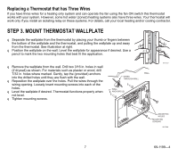
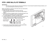
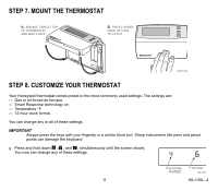
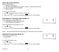
STEP 4. WIRE WALLPLATE TERMINALS IMPORTANT All wiring must comply with local codes and ordinances. If unsure about household wiring procedures, call your local heating/air-conditioning contractor. Refer to the labels you placed on the wires when you removed the old thermostat (see illustration). q Match the letter of your old thermostat wire with the corresponding terminal letter on your new thermostat. Refer to Table 2. q Remove the factory-installed jumper connecting terminals R and RC if wires are connected to both of those terminals. q For wiring diagrams, if needed, see pages 22-23. R q Loosen the terminal screws. Slip each wire beneath its matching W Y G terminal. Wraparound and straight connections are both acceptable, (see illustration). Tighten the terminals. FOR WRAPAROUND INSERTION STRIP 7/16 IN. (11 MM). FOR STRAIGHT INSERTION STRIP 5/16 IN. (8 MM). M4826 q Plug the hole in the wall with insulation to help prevent drafts from adversely affecting thermostat operation. M16425 69-1199-4 8
-
 1
1 -
2
-
 3
3 -
 4
4 -
 5
5 -
 6
6 -
 7
7 -
 8
8 -
 9
9 -
 10
10 -
 11
11 -
 12
12 -
 13
13 -
14
-
15
-
16
-
17
-
18
-
19
-
20
-
21
-
22
-
23
-
24
 |
 |
