Honeywell HY-047B User Guide - Page 2
D. Placing the Remote Control in the Storage Area - instructions
 |
UPC - 092926345501
View all Honeywell HY-047B manuals
Add to My Manuals
Save this manual to your list of manuals |
Page 2 highlights
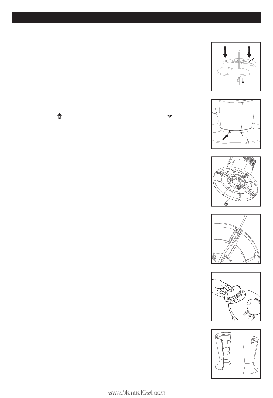
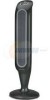
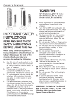
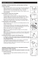
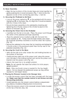
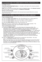
ASSEMBLY INSTRUCTIONS ASSEMBLY INSTRUCTIONS FOR LOW FAN HEIGHT OPTION A. Base Assembly •Align the two portions of the circular base and snap together by gently pushing the 4 round extrusions (Fig. 1, Item A) into the adjacent circles of the connecting piece. (Fig. 1, Item B) • Place the power cord through the center of the 2 halves of the base assembly. B. Securing the Tower Fan to the Base Fig. 1 A B Base Assembly •Carefully turn the fan on its side. Fig. 2 • Pull any slack out of the power cord. Align the base arrow marked as with the tower fan arrow marked as . Rotate the base clockwise to lock the tower fan in place. (Fig. 2) •Secure the base assembly to the tower fan by inserting and tightening the thumb screw to the bottom of the base. (Fig. 3) C. Securing the Cord to the Base • With the fan on its side, locate the cord holding bracket on the bottom of the base. Fig. 3 • Gently pull any slack out of the power cord, place the power cord securely in the power cord holding bracket and secure the power cord bracket over the power cord. (Fig. 4) • Return the tower fan to its upright position. Note: Do not operate the tower fan unless it is in its proper, upright position. Note: Only one thumb screw is needed for the low height option. Fig. 4 Do not discard the additional screws as they will be needed for Tall Height Option D. Placing the Remote Control in the Storage Area • Locate the remote control that has been provided with the tower fan. Make sure that the remote control is not thrown out with the packing materials. • Install batteries into the remote control battery compartment Fig. 5 (see Battery Installation/Replacement Instructions). • Place the remote control in the recessed remote holder located on the top of the fan. (Fig. 5) ASSEMBLY INSTRUCTIONS FOR TALL FAN HEIGHT OPTION (Using pedestal height extender) NOTE: Product is most stable when pedestal extender is not used. A. Pedestal Assembly •Line up the left and right pedestal assembly and firmly snap together. (Fig. 6). Fig. 6 Pedestal Assembly
-
 1
1 -
 2
2 -
 3
3 -
 4
4 -
 5
5 -
 6
6 -
 7
7 -
 8
8 -
9
-
10
-
11
-
12
-
13
-
14
-
15
-
16
-
17
-
18
-
19
-
20
-
21
-
22
-
23
-
24
-
25
-
26
-
27
-
28
-
29
-
30
-
31
-
32
-
33
-
34
-
35
-
36
 |
 |