Honeywell T7351F2010 Installation Instructions - Page 1
Honeywell T7351F2010 - Digital Thermostat, 3h Manual
 |
View all Honeywell T7351F2010 manuals
Add to My Manuals
Save this manual to your list of manuals |
Page 1 highlights
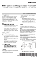
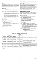
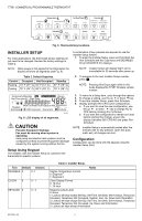
T7351 Commercial Programmable Thermostat FOR SINGLE- OR MULTI-STAGE CONVENTIONAL/HEAT PUMP SYSTEMS APPLICATION The T7351 Commercial Programmable Thermostat controls 24 Vac commercial single zone heating, ventilating and air conditioning (HVAC) equipment. The T7351 consists of a thermostat and subbase. The thermostat includes the display and keypad for 7-day programming. The subbase includes equipment control connections. The subbase mounts on the wall and the thermostat mounts to the subbase. MERCURY NOTICE If this control is replacing a control that contains mercury in a sealed tube, do not place your old control in the trash. Dispose of properly. Contact your local waste management authority for instructions regarding recycling and the proper disposal of an old control. If you have questions, call Honeywell Customer Care Center at 1-800-468-1502. INSTALLATION When Installing this Product... 1. Read these instructions carefully. Failure to follow them could damage the product or cause a hazardous condition. 2. Check ratings given in instructions and on the product to ensure the product is suitable for your application. 3. Installer must be a trained, experienced service technician. 4. After installation is complete, check out product operation as provided in these instructions. CAUTION Electrical Shock or Equipment Damage Hazard. Can shock individuals or short equipment circuitry. Disconnect power supply before installation. Location Do not install the thermostat where it can be affected by: - drafts, or dead spots behind doors and in corners. - hot or cold air from ducts. - radiant heat from sun or appliances. INSTALLATION INSTRUCTIONS - concealed pipes and chimneys. - unheated (uncooled) areas such as an outside wall behind the thermostat. IMPORTANT To avoid electrical interference, which can cause erratic performances, keep wiring runs as short as possible and do not run thermostat wires adjacent to the line voltage electrical distribution systems. Use shielded cable. The cable shield must be grounded only at the controlled equipment case. Subbase WHEN USED TO SENSE ROOM TEMPERATURE Install the thermostat about 5 ft. (1.5m) above the floor in an area with good air circulation at average temperature. (See Fig. 1.) WHEN NOT USED TO SENSE ROOM TEMPERATURE When using the remote-mounted temperature (and humidity) sensor(s) to sense ambient conditions, install the thermostat in an area that is accessible for setting and adjusting the temperature and settings. Install the remote-mounted sensor(s) about 5 ft. (1.5m) above the floor in an area with good air circulation at average temperature (See Fig. 1). If multiple remote sensors are required, they must be arranged in a temperature averaging network consisting of four sensors (See Fig. 2). NOTE: Only TR21 models with no setpoint adjustment can be used for temperature averaging. YES NO NO NO 5 FEET (1.5 METERS) M4823A Fig. 1. Typical location of thermostat or remote-mounted sensor. Place Bar Code Here 62-0258-05
-
 1
1 -
 2
2 -
 3
3 -
 4
4 -
 5
5 -
 6
6 -
 7
7 -
8
-
9
-
10
-
11
-
12
-
13
-
14
-
15
-
16
 |
 |