Honeywell T7351F2010 Installation Instructions - Page 2
Mounting Subbase, Mounting Thermostat on Subbase Fig.
 |
View all Honeywell T7351F2010 manuals
Add to My Manuals
Save this manual to your list of manuals |
Page 2 highlights
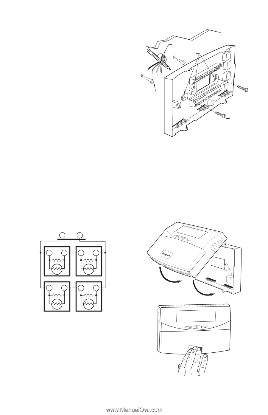
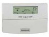
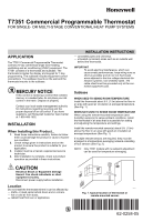
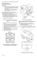
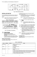
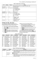
T7351 COMMERCIAL PROGRAMMABLE THERMOSTAT Mounting Subbase The subbase mounts horizontally. IMPORTANT • When using the internal temperature or humidity sensor, the device must be mounted horizontally (with the LCD facing upwards). Precise leveling is not needed. • When using remote room temperature and humidity sensors, thermostat mounting orientation does not matter. WIRES THROUGH WALL MOUNTING HOLES Wall mounting (using standard drywall screws) is standard. Mounting to a 2 in. by 4 in. (50.8 mm by 101.6 mm) wiring box can be accomplished: - for a horizontal box, no extra hardware is required. - for a vertical box, part 209651A is required. - Mount to European standard wall box (having 2.4 in. (60.3 mm) between mounting screws in a horizontal line) with or without adaptive hardware. 1. Position and level the subbase. WALL ANCHORS (2) MOUNTING SCREWS M19608 NOTE: A level wallplate is only for appearance. The thermostat functions properly when not level. 2. Use a pencil to mark the mounting holes. (See Fig. 3). 3. Remove the subbase from the wall and drill two 3/ 16 in. (4.8 mm) holes in the wall (if drywall) as marked. For firmer material such as plaster or wood, drill two 7/32 in. (5.6 mm) holes. 4. Gently tap anchors (provided) into the drilled holes until flush with the wall. 5. Position the subbase over the holes, pulling wires through the wiring opening. 6. Loosely insert the mounting screws into the holes. 7. Tighten mounting screws. Fig. 3. Mounting the subbase. Mounting Thermostat on Subbase (Fig. 4) With the subbase installed, mount the thermostat: 1. Engage top subbase tabs into the thermostat top. 2. Swing the thermostat down. 3. Press the lower edge of the case to latch. NOTE: To remove the thermostat from the wall, first pull out at the bottom of the thermostat; then remove the top. A. ENGAGE TABS AT TOP OF THERMOSTAT AND SUBBASE OR WALLPLATE. TR21 SUBBASE T4 T3 TR21 T T T T TR21 TR21 T T T T M29184 Fig. 2. Four TR21 Sensors providing temperature averaging network for T7351 Thermostat. B. PRESS LOWER EDGE OF CASE TO LATCH. 62-0258-05 M19609 Fig. 4. Mounting thermostat on subbase. 2
-
 1
1 -
 2
2 -
 3
3 -
 4
4 -
 5
5 -
 6
6 -
 7
7 -
 8
8 -
9
-
10
-
11
-
12
-
13
-
14
-
15
-
16
 |
 |