Honeywell T8401C1015 Installation Instructions - Page 2
Setting Fan Operation Fuel Switch, Wiring - electronic thermostat
 |
View all Honeywell T8401C1015 manuals
Add to My Manuals
Save this manual to your list of manuals |
Page 2 highlights
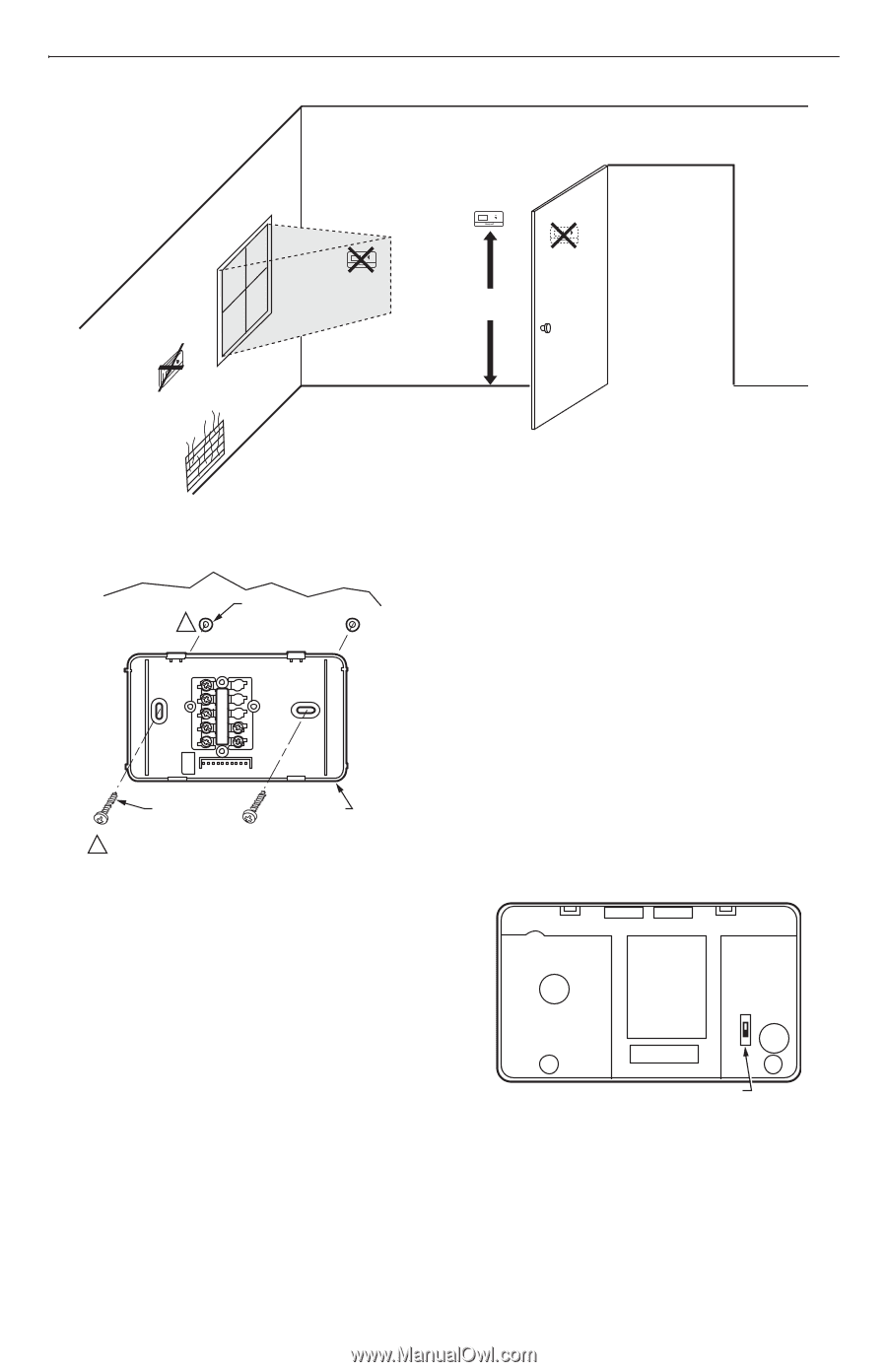
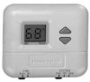
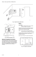
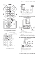
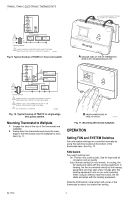
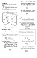
T8400C, T8401C ELECTRONIC THERMOSTATS YES NO NO 5 FEET [1.5 METERS] NO M11338 Fig. 1. Typical location of thermostat. Wiring WALL 1 WALL ANCHORS (2) IMPORTANT Use an 18-gauge maximum wire to wire the T8400C and T8401C Thermostats. All wiring must comply with local electrical codes and ordinances. Disconnect the power supply to prevent electrical shock or equipment damage. NOTE: To ensure proper mounting of thermostat, restrict all wiring to the shaded area. See Fig. 4. MOUNTING SCREWS (2) WALLPLATE 1 WHEN USING WALL ANCHORS, DRILL 3/16 INCH HOLES FOR DRYWALL, 7/32 INCH HOLES FOR PLASTER OR WOOD. M12202A Fig. 2. Mounting wallplate to wall. The shape of the terminals permits insertion of straight or wraparound wiring connections; either method is acceptable. See Fig. 5. Refer to Fig. 6 through 10 for typical wiring hookups. Setting Fan Operation (Fuel) Switch The fan operation (fuel) switch is preset at the factory in the F position. See Fig. 3. This is the correct setting for most systems. If this system is an electric heat system, set the switch to the E position. The E setting allows the fan to turn on immediately with the heating or cooling equipment in a system where the G terminal is connected. E F FAN OPERATION (FUEL) SWITCH M12580 Fig. 3. Fan operation (fuel) switch. 69-1740 2
-
 1
1 -
 2
2 -
 3
3 -
 4
4 -
 5
5 -
 6
6 -
 7
7 -
 8
8
 |
 |