Honeywell T8401C1015 Installation Instructions - Page 4
Operation - manual
 |
View all Honeywell T8401C1015 manuals
Add to My Manuals
Save this manual to your list of manuals |
Page 4 highlights
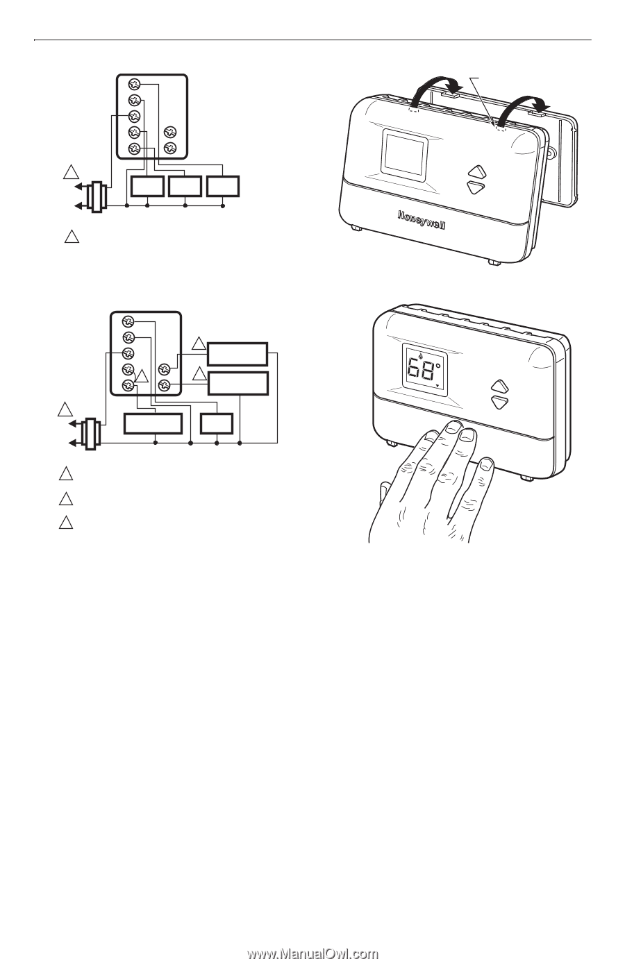
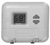
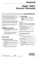
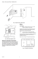
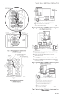
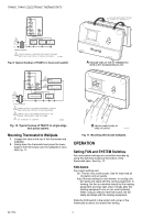
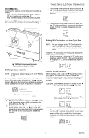
T8400C, T8401C ELECTRONIC THERMOSTATS G C R W B Y O 1 L1 (HOT) 24V L2 TRANSFORMER HEAT RELAY COOL RELAY FAN RELAY 1 POWER SUPPLY. PROVIDE DISCONNECT MEANS AND OVERLOAD PROTECTION AS REQUIRED. M20881 Fig. 9. Typical hookup of T8401C in heat-cool system. DASHED LINES INDICATE TABS ON BACK OF THERMOSTAT Set Room AuFtoANOn CoSoYl SOTffEMHeat A ENGAGE TABS AT TOP OF THERMOSTAT WITH SLOTS ON MOUNTING PLATE. G C R W 3 Y 2 HEAT CHANGEOVER B 2 COOL O CHANGEOVER 1 L1 (HOT) 24V L2 TRANSFORMER COMPRESSOR FAN RELAY 1 POWER SUPPLY. PROVIDE DISCONNECT MEANS AND OVERLOAD PROTECTION AS REQUIRED. 2 CAN BE USED FOR CHANGEOVER VALVE ON SINGLE-STAGE HEAT PUMP SYSTEMS. 3 FIELD INSTALLED JUMPER. M20882 Fig. 10. Typical hookup of T8401C in single-stage heat pump system. Mounting Thermostat to Wallplate 1. Engage the tabs at the top of the thermostat and wallplate. 2. Swing down the thermostat and press the lower edge of the thermostat onto the wallplate to latch. See Fig. 11. Set Room AuFtAoNOn CooSlYOSfTf EHMeat B PRESS LOWER EDGE OF CASE TO LATCH. M14677A Fig. 11. Mounting thermostat wallplate. OPERATION Setting FAN and SYSTEM Switches Fan and system settings are controlled manually by using the switches located at the bottom of the thermostat case. See Fig. 12. FAN Switch Fan switch settings are: On: The fan runs continuously. Use for improved air circulation and air quality. Auto: Normal setting for most homes. In cooling, the fan starts and stops with the cooling equipment. In heating, the fan is controlled directly by the heating equipment and may start a few minutes after the heating equipment turns on (on most systems). When using an electric heat thermostat, the fan starts and stops with the heating equipment. Slide the FAN switch in the bottom left corner of the thermostat to select the desired fan setting. 69-1740 4
-
 1
1 -
 2
2 -
 3
3 -
 4
4 -
 5
5 -
 6
6 -
 7
7 -
 8
8
 |
 |