Honeywell T8775C1005 Installation Instructions - Page 1
Honeywell T8775C1005 - Digital Round 24V Manual
 |
UPC - 085267244183
View all Honeywell T8775C1005 manuals
Add to My Manuals
Save this manual to your list of manuals |
Page 1 highlights
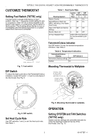
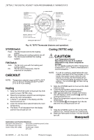
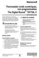
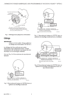
T8775A,C The Digital Round™ Non-Programmable Thermostats The T8775A,C Thermostats provide single-stage temperature control for 24V systems. The T8775A,C models include a thermostat, wallplate (for wiring and mounting thermostat), mounting screws, wall anchors, and a 4074 FAB resistor. MERCURY NOTICE If this control is replacing a control that contains mercury in a sealed tube, do not place your old control in the trash. Contact your local waste management authority for instructions regarding recycling and the proper disposal of an old control containing mercury in a sealed tube. INSTALLATION INSTRUCTIONS Location Install the thermostat about 5 ft (1.5m) above the floor in an area with good air circulation at average temperature. Do not install the thermostat where it can be affected by: - drafts or dead spots behind doors and in corners. - hot or cold air from ducts. - radiant heat from the sun or appliances. - concealed pipes and chimneys. - unheated (uncooled) areas such as an outside wall behind the thermostat. Mounting Wallplate to Wall Mount the T8775A,C wallplate, with the screws provided. See Fig. 1. INSTALLATION When Installing this Product... 1. Read these instructions carefully. Failure to follow them could damage the product or cause a hazardous condition. 2. Check the ratings given in the instructions and on the product to make sure the product is suitable for your application. 3. Installer must be a trained, experienced service technician. 4. After installation is complete, check out product operation as provided in these instructions. CAUTION Electrical Shock or Equipment Damage Hazard. Can shock individuals or short equipment circuitry. Disconnect power supply before installation. ® U.S. Registered Trademark • Patents Pending © 2004 Honeywell International Inc. All Rights Reserved WALL ANCHORS (2) WALL PLATE 1 WIRING HOLE 1 INCH SCREW (2) M19499 1 WHEN USING WALL ANCHORS, DRILL 3/16 IN. HOLES FOR DRYWALL, 7/32 IN. HOLES FOR PLASTER. Fig. 1. Mounting wallplate to wall. 69-1677EF-1
-
 1
1 -
 2
2 -
 3
3 -
 4
4 -
 5
5 -
 6
6 -
 7
7 -
8
-
9
-
10
-
11
-
12
 |
 |