Honeywell T8775C1005 Installation Instructions - Page 3
Customize Thermostat, Operation - manual
 |
UPC - 085267244183
View all Honeywell T8775C1005 manuals
Add to My Manuals
Save this manual to your list of manuals |
Page 3 highlights
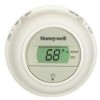
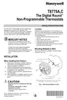
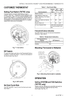
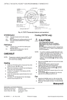
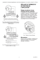
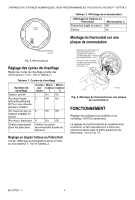
T8775A,C THE DIGITAL ROUND™ NON-PROGRAMMABLE THERMOSTATS CUSTOMIZE THERMOSTAT Setting Fuel Switch (T8775C only) The fuel switch is preset at the factory in the F position. See Fig. 7. This is the correct setting for gas or oil systems. If the T8775C is being installed on an electric heat system, or a heat pump, set the switch to the E position. The E setting allows the fan to turn on immediately with the heating equipment in a system where the G terminal is connected. Table 1. Heat Cycle Rate. Heating System Cycles DIP DIP Per Switch Switch Hour 1 2 Steam, Gravity 1 On On High Efficiency Warm Air 3 (90%+ efficiency), Hot Water, Heat Pump Off On Gas or Oil Warm Air (factory 6 setting) Off Off Electric Warm Air 9 On Off In Floor Radiant Heat Check with manufacturer for recommended cycle rate. FUEL SWITCH Fig. 7. Fuel switch. M19497 DIP Switch To adjust the heat cycle rate or the Fahrenheit/Celsius indication, locate DIP switch 1, 2 and 3 on the back of the thermostat. See Fig. 8. BACK OF THERMOSTAT Fahrenheit/Celsius Indication Use DIP switch 3 to set the desired temperature indication. See Table 2. Table 2. Temperature Indication. Fahrenheit/Celsius Display Fahrenheit (factory setting) Off Celsius On DIP Switch 3 Mounting Thermostat to Wallplate ENGAGE TABS AT BOTTOM OF THERMOSTAT AND WALL PLATE. PRESS UPPER EDGE OF CASE TO LATCH ON 123 DIP SWITCH M19567 Fig. 8. DIP switch. Set Heat Cycle Rate Use DIP switches 1 and 2 to set the heat cycle rate. See Table 1. M19498 Fig. 9. Mounting thermostat to wallplate. OPERATION Setting SYSTEM and FAN Switches (T8775C only) System and fan settings are controlled manually by using the switches located at the top of the thermostat. See Fig. 10. 3 69-1677EF-1
-
 1
1 -
 2
2 -
 3
3 -
 4
4 -
 5
5 -
 6
6 -
 7
7 -
 8
8 -
 9
9 -
10
-
11
-
12
 |
 |