Honeywell T8775C1005 Installation Instructions - Page 2
Wiring - round digital thermostat
 |
UPC - 085267244183
View all Honeywell T8775C1005 manuals
Add to My Manuals
Save this manual to your list of manuals |
Page 2 highlights
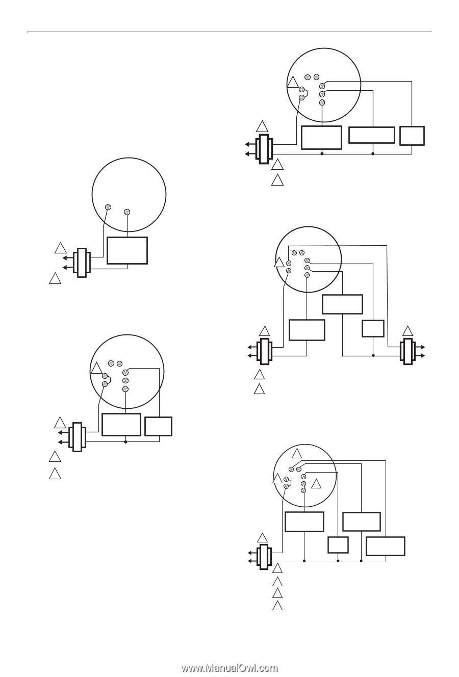
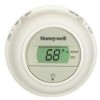
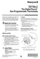
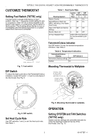
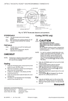
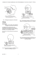
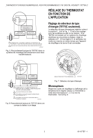
T8775A,C THE DIGITAL ROUND™ NON-PROGRAMMABLE THERMOSTATS Wiring IMPORTANT Use 18-gauge wire to wire the T8775A,C Thermostats. All wiring must comply with local electrical codes and ordinances. Disconnect the power supply to prevent electrical shock or equipment damage. Refer to Fig. 2 through 6 for typical wiring hookups. O B 2 Rc G R Y W 1 HEATING COMPRESSOR FAN RELAY OR CONTACTOR RELAY VALVE COIL R W 1 POWER SUPPLY. PROVIDE DISCONNECT MEANS AND OVERLOAD PROTECTION AS REQUIRED. 2 FACTORY INSTALLED JUMPER. M19515 Fig. 4. Typical hookup of T8775C in heat-cool system with single transformer. HEATING 1 RELAY OR VALVE COIL 1 POWER SUPPLY. PROVIDE DISCONNECT MEANS AND OVERLOAD PROTECTION AS REQUIRED. M19513 Fig. 2. Typical hookup of T8775A in a heat-only system. O B 2 Rc G R Y W 1 HEATING RELAY OR VALVE COIL FAN RELAY B Rc G 2 R Y W COMPRESSOR CONTACTOR HEATING 1 RELAY OR VALVE COIL FAN RELAY 1 1 POWER SUPPLY. PROVIDE DISCONNECT MEANS AND OVERLOAD PROTECTION AS REQUIRED. 2 REMOVE FACTORY INSTALLED JUMPER BETWEEN R AND RC. M19517 Fig. 5. Typical hookup of T8775C in heat-cool system with two transformers. 1 POWER SUPPLY. PROVIDE DISCONNECT MEANS AND OVERLOAD PROTECTION AS REQUIRED. 2 FACTORY INSTALLED JUMPER. M19514 Fig. 3. Typical hookup of T8775C in heat-only system with fan. 69-1677EF-1 2 4 O Rc 2 R B G Y3 W COMPRESSOR CONTACTOR HEAT CHANGEOVER VALVE 1 FAN COOL RELAY CHANGEOVER VALVE 1 POWER SUPPLY. PROVIDE DISCONNECT MEANS AND OVERLOAD PROTECTION AS REQUIRED. 2 FACTORY INSTALLED JUMPER. 3 USE A JUMPER WIRE (NOT SUPPLIED) TO CONNECT W TO Y. 4 USE EITHER O OR B FOR HEAT PUMP CHANGEOVER. M19516 Fig. 6. Typical hookup of T8775C in single-stage heat pump system.
-
 1
1 -
 2
2 -
 3
3 -
 4
4 -
 5
5 -
 6
6 -
 7
7 -
 8
8 -
9
-
10
-
11
-
12
 |
 |