Hoover U6425 Manual - Page 4
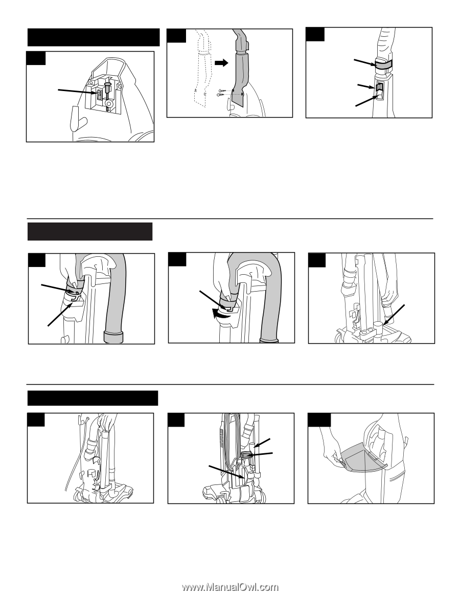
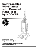
Hose must be connected as shown for, operations. - switch
 |
View all Hoover U6425 manuals
Add to My Manuals
Save this manual to your list of manuals |
Page 4 highlights
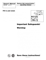
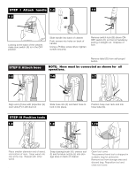
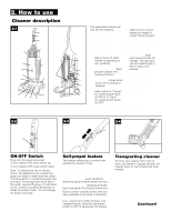
STEP I Attach handle 1-3 1-2 1-4 D A B C Looking at the back of the cleaner, make sure switch (A) is in the OFF position. STEP II Attach hose Slide handle into back of cleaner. Push screws into holes on back of handle. Using a Phillips screw driver, tighten screws securely. Remove switch lock (B) above ONOFF switch (C) on front of handle by pulling it straight out. Dispose of lock. If switch lock has come off during assembly, make sure switch is in OFF position (down) before plugging cord into electrical outlet. Remove label (D) from self-propel button. NOTE: Hose must be connected as shown for all operations. 1-5 1-6 1-7 E F G F Align end of hose with projection (E) over slots (F) in dirt duct on back of handle. Slide hose into (F) and twist hose to lock it into place. Position hose over rack and into hose tube (G). STEP III Position tools 1-8 1-9 J 1-10 I H Place smaller diameter end of wand, into bottom of rack. Snap wand into clip at the top. Repeat with other wand. 4 Snap dusting brush (H), crevice tool (I) and furniture nozzle (J) into storage area on back of cleaner. Open tool cover. The powered hand tool is shipped in a plastic bag for protection. Remove tool from storage area and discard bag. Reposition tool and close tool cover.
-
 1
1 -
 2
2 -
 3
3 -
 4
4 -
 5
5 -
 6
6 -
 7
7 -
 8
8 -
 9
9 -
 10
10 -
11
-
12
-
13
-
14
-
15
-
16
-
17
-
18
-
19
-
20
-
21
-
22
-
23
-
24
-
25
-
26
-
27
-
28
-
29
-
30
 |
 |