Husqvarna 128DJx Owners Manual - Page 12
Fitting a blade guard, grass, blade and grass cutter, itting blades and trimmer, heads, WARNING,
 |
View all Husqvarna 128DJx manuals
Add to My Manuals
Save this manual to your list of manuals |
Page 12 highlights
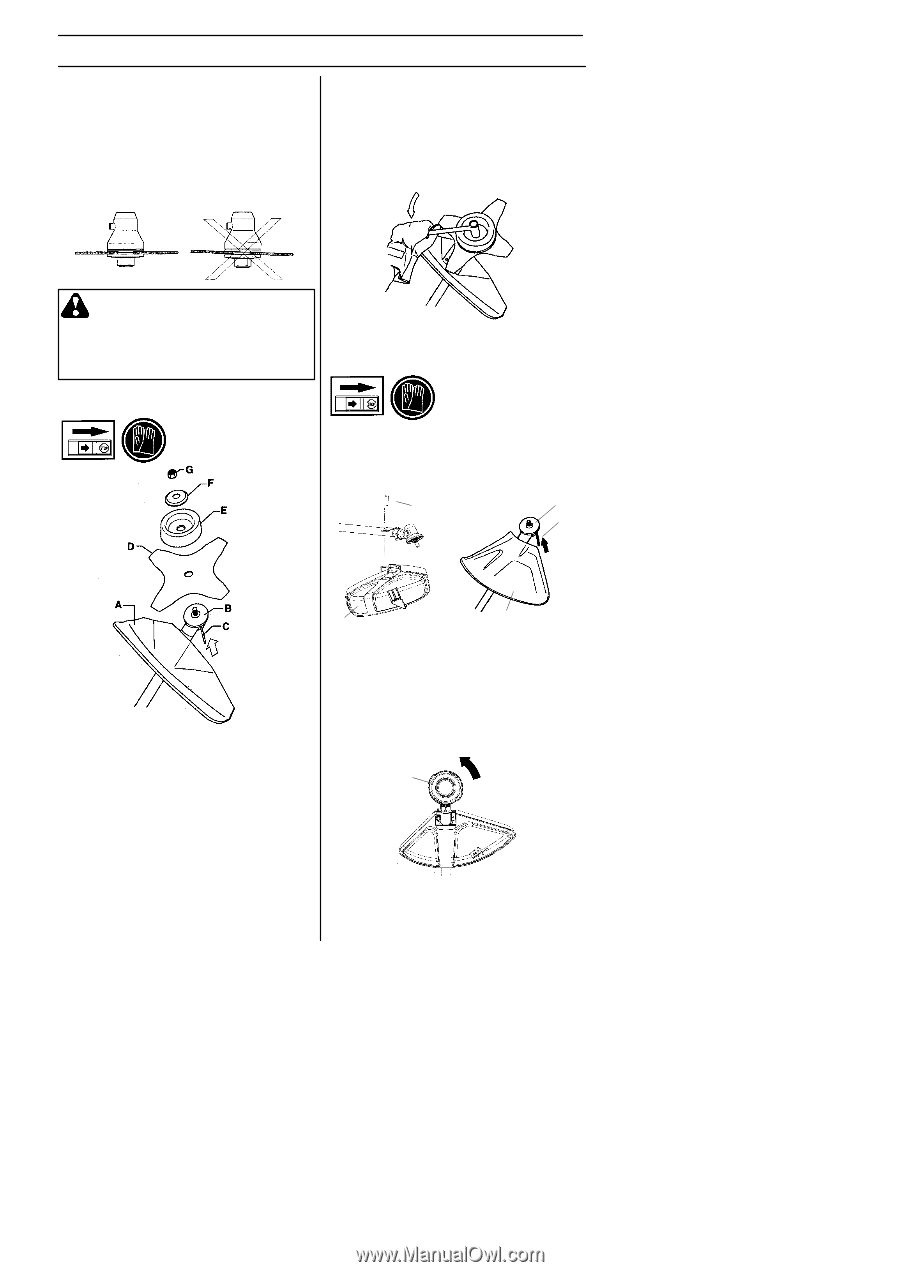
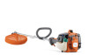
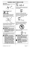
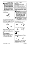
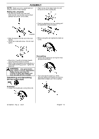
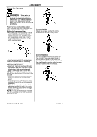
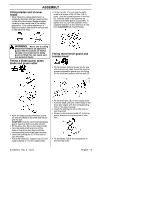
ASSEMBLY Fitting blades and trimmer heads S When fitting the cutting attachment it is extremely important that the raised section on the drive disc/support flange engages correctly in the centre hole of the cutting attachment. If the cutting attachment is fitted incorrectly it can result in serious and/ or fatal personal injury. S Fit the nut (G). The nut must be tightened to a torque of 35--50 Nm (3.5--5 kpm). Use the socket spanner in the tool kit. Hold the shaft of the spanner as close to the blade guard as possible. To tighten the nut, turn the spanner in the opposite direction to the direction of rota- tion (CAUTION! left--hand thread). WARNING: Never use a cutting attachment without an approved guard. See the section on Technical data. If an incorrect or faulty guard is fitted this can cause serious personal injury. Fitting a blade guard, grass blade and grass cutter Fitting the trimmer guard and trimmer head S Fit the correct trimmer guard (A) for use with the trimmer head. Hook the trimmer guard/combination guard onto the fitting on the shaft and secure with the bolt (D). D B C S Hook the blade guard/combination guard (A) onto the fitting on the shaft and secure with the bolt. CAUTION! Use the recommended blade guard. See the Technical data section. S Fit the drive disc (B) on the output shaft. S Turn the blade shaft until one of the holes in the drive disc aligns with the corresponding hole in the gear housing. S Insert the locking pin (C) in the hole to lock the shaft. S Place the blade (D), support cup (E) and support flange (F) on the output shaft. A A S Fit the drive disc (B) on the output shaft. S Turn the shaft until one of the holes in the drive disc aligns with the corresponding hole in the gear housing. S Insert the locking pin (C) in the hole to lock the shaft. S Screw on the trimmer head (H) in the opposite direction to the direction of rotation. H S To dismantle, follow the instructions in the reverse order. 577387001 Rev. 2 1/6/11 English--- 12
-
 1
1 -
2
-
3
-
4
-
5
-
6
-
 7
7 -
 8
8 -
 9
9 -
 10
10 -
 11
11 -
 12
12 -
 13
13 -
 14
14 -
 15
15 -
 16
16 -
 17
17 -
18
-
19
-
20
-
21
-
22
-
23
-
24
-
25
-
26
-
27
-
28
-
29
 |
 |