Husqvarna PZ6029D Owners Manual - Page 18
CONTROLS, Control Locations
 |
View all Husqvarna PZ6029D manuals
Add to My Manuals
Save this manual to your list of manuals |
Page 18 highlights
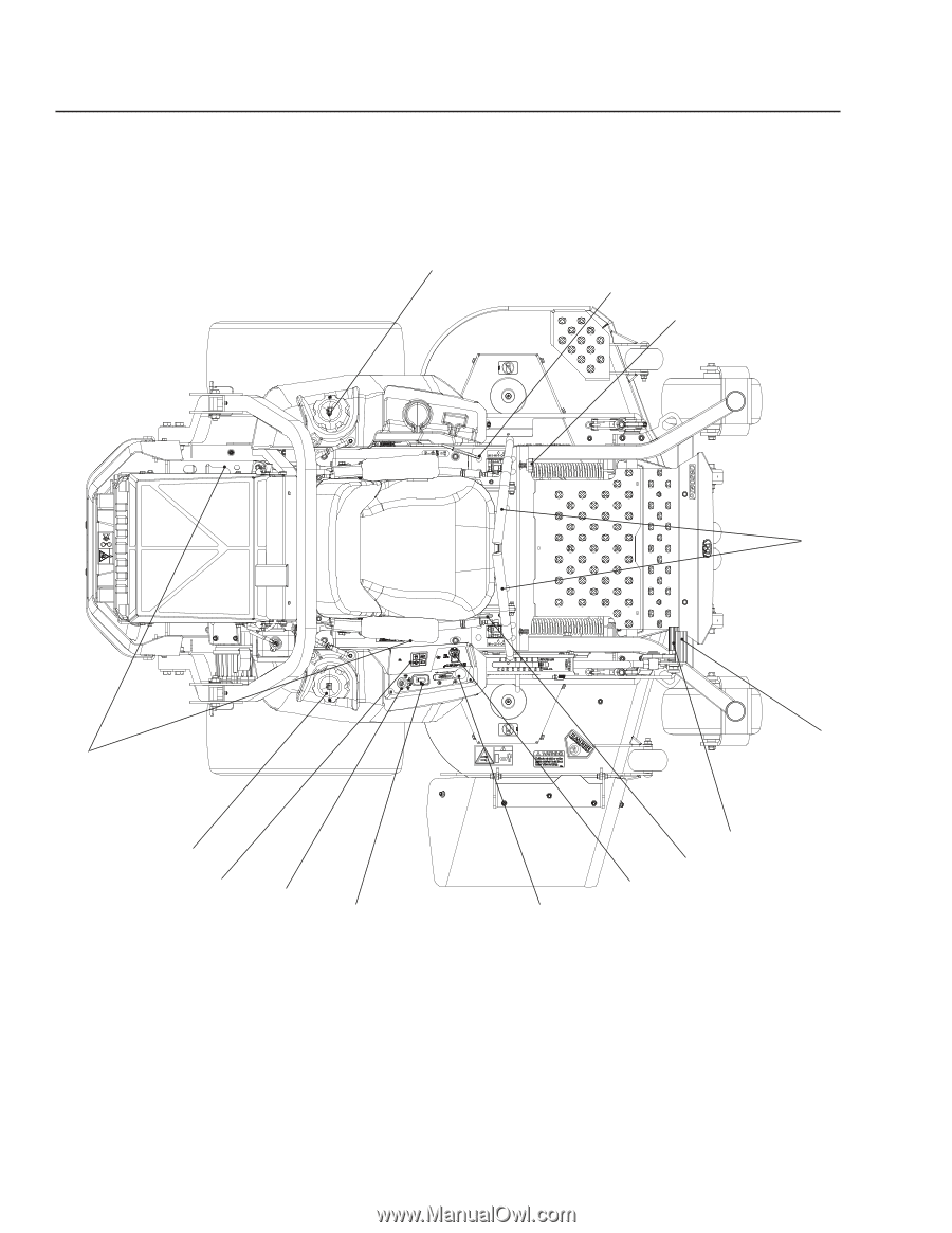
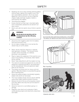
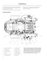
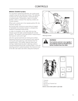
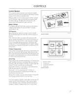
CONTROLS This operator's manual describes the Husqvarna Zero Turn Rider. The rider is fitted with a Kubota engine developing 29 horse power*. Transmission from the engine is made via belt-driven hydraulic pumps. Using the left and right steering controls, the flow is regulated and thereby the direction and speed. Control Locations 4 3 2 1 14 5 6 7 8 9 1. Motion control levers 2. Tracking knob 3. Parking brake 4. Fuel tank cap, left 5. Fuses 6. Fuel tank cap, right 7. Control Module 18 8. Ignition switch 9. Hour meter 10. Throttle control 11. Blade switch 12. Seat adjustment 13. Deck release 14. Deck lift 13 12 11 10 *The power rating of the engines indicated is the average net power output (at specified rpm) of a typical production engine for the engine model measured to SAE standard J1349/ISO1585. Mass production engines may differ from this value. Actual power output for the engine installed in the final machine will depend on the operating speed, environmental conditions and other variables.
-
 1
1 -
2
-
3
-
4
-
5
-
6
-
7
-
8
-
9
-
10
-
11
-
12
-
 13
13 -
 14
14 -
 15
15 -
 16
16 -
 17
17 -
 18
18 -
 19
19 -
 20
20 -
 21
21 -
 22
22 -
 23
23 -
24
-
25
-
26
-
27
-
28
-
29
-
30
-
31
-
32
-
33
-
34
-
35
-
36
-
37
-
38
-
39
-
40
-
41
-
42
-
43
-
44
-
45
-
46
-
47
-
48
-
49
-
50
-
51
-
52
-
53
-
54
-
55
-
56
-
57
-
58
-
59
-
60
-
61
-
62
-
63
-
64
-
65
-
66
-
67
-
68
-
69
-
70
-
71
-
72
 |
 |