Husqvarna ST 151 Owners Manual - Page 14
Servicing the Spark Plug
 |
View all Husqvarna ST 151 manuals
Add to My Manuals
Save this manual to your list of manuals |
Page 14 highlights
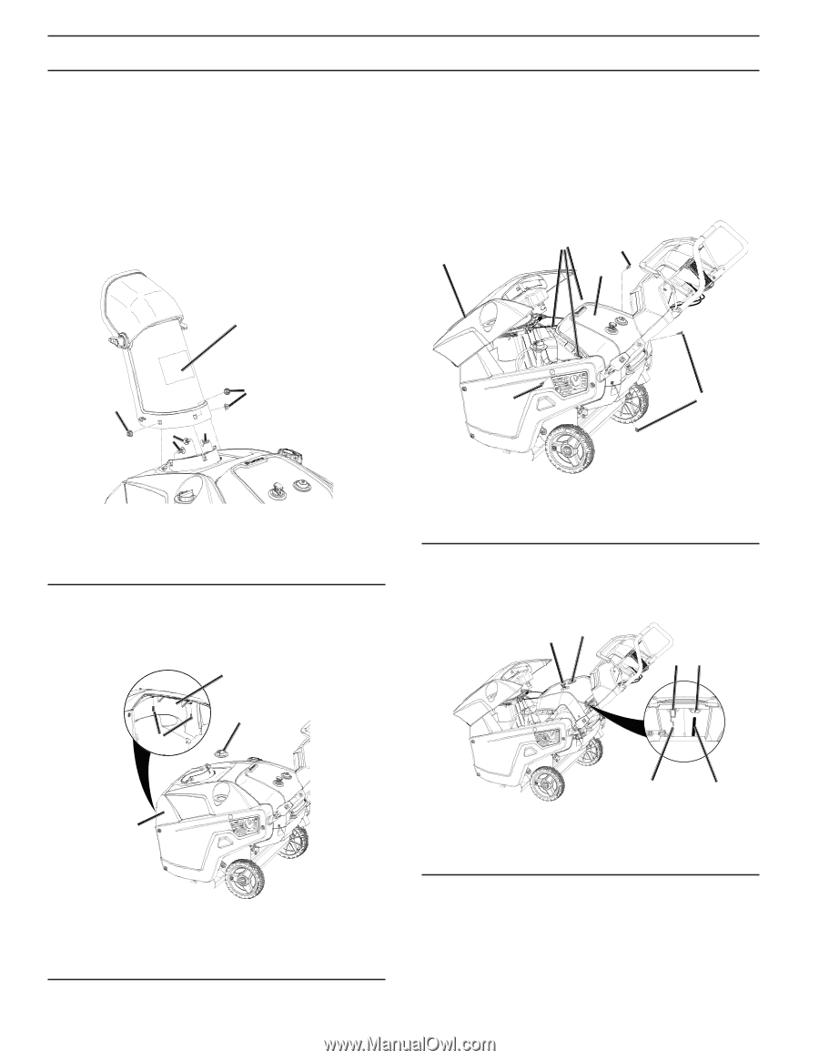
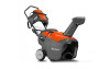
MAINTENANCE Servicing the Spark Plug Use a NGK BPR6ES, Champion RN9YC, or BOSCH WR6DC spark plug or equivalent. 1. Move snow thrower to a level surface. 2. Run snow thrower until all fuel has been depleted. 3. Wait until engine is cool. 4. Rotate the discharge chute so that it faces forward. 5. Remove the discharge chute by removing the three carriage bolts and three flange nuts (Figure 27). 8. Unsnap top cover by firmly pulling upwards at the rear section of the cover disengaging the three clips (Figure 29). 9. Shift top cover until fuel tank is clear of the rear upper cover and set top cover to the side of the unit. 10. Temporarily reinstall oil fill cap to prevent foreign object from entering the engine. 11. Remove 2 screws in the side cover and rear covers on both sides. 2 3 1 4 1 3 3 22 3 3 Figure 27 1. Discharge chute 2. Carriage bolts 3. Flange nuts 6. Remove two screws in plenum that hold top cover (Figure 28). 7. Remove the oil fill cap. 2 3 1 1. Top cover 2. Clips Figure 29 3. Screw 4. Rear upper cover 12. Unplug electrical wires on back of ignition switch (Figure 30). 13. Pull tube off the back of the primer bulb. 24 24 1 3 4 Figure 30 1. Electrical wires 3. Tube 2. Ignition switch 4. Primer bulb 1. Screw 2. Plenum Figure 28 3. Oil fill cap 4. Top cover 14. Lift rear upper cover and lay it to the side of the unit. IMPORTANT: The recoil rope will still be attached to the upper cover. 14
-
 1
1 -
2
-
3
-
4
-
5
-
6
-
7
-
8
-
 9
9 -
 10
10 -
 11
11 -
 12
12 -
 13
13 -
 14
14 -
 15
15 -
 16
16 -
 17
17 -
 18
18 -
 19
19 -
20
-
21
-
22
-
23
-
24
 |
 |