Husqvarna ST 151 Owners Manual - Page 5
Setup, ASSEMBLY
 |
View all Husqvarna ST 151 manuals
Add to My Manuals
Save this manual to your list of manuals |
Page 5 highlights
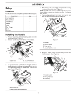
ASSEMBLY Setup Loose Parts Use the chart below to verify that all parts have been shipped. Description Qty. Carriage bolts 4 Shoulder Bolt 1 Flange nuts 4 Washer 1 Knob 1 Cap Plunger 1 Chute 1 Deflector 1 Installing the Handle 1. Remove temporary cable ties holding cables at handle adjustment holes (Figure 2). 2. Release handle adjustment levers on both sides. 1 2 4. Pull up and push down slightly on the handle to verify handle is locked into place (Figure 4). NOTE: If handle feels unsecure with the adjustment levers closed, tighten adjustment handle nuts until the handle feels secure. 5. Remove the cardboard from recoil start handle and feed the recoil rope through the rope guide. 1 2 3 4 Figure 4 1. Handle 2. Recoil handle 3. Rope guide 4. Adjustment lever nut 6. Snap two rotator cables and one wiring harness into the three cable clips (Figure 5). 1 Figure 2 2 1. Cable ties 2. Adjustment lever 3. Lift operator handle up to the desired height, and close adjustment lever ensuring the positioning pin on the lower handle engages one of the three holes on the upper handle (Figure 3). 2 1 3 Figure 5 1. Rotator cable 2. Wiring harness 3. Cable clip Figure 3 1. Positioning pin 2. Upper handle adjustment hole 5
-
 1
1 -
 2
2 -
 3
3 -
 4
4 -
 5
5 -
 6
6 -
 7
7 -
 8
8 -
 9
9 -
 10
10 -
 11
11 -
12
-
13
-
14
-
15
-
16
-
17
-
18
-
19
-
20
-
21
-
22
-
23
-
24
 |
 |
