Husqvarna ST131 Owners Manual - Page 17
Install the spark plug and torque it to 20-22 ft-lb
 |
View all Husqvarna ST131 manuals
Add to My Manuals
Save this manual to your list of manuals |
Page 17 highlights
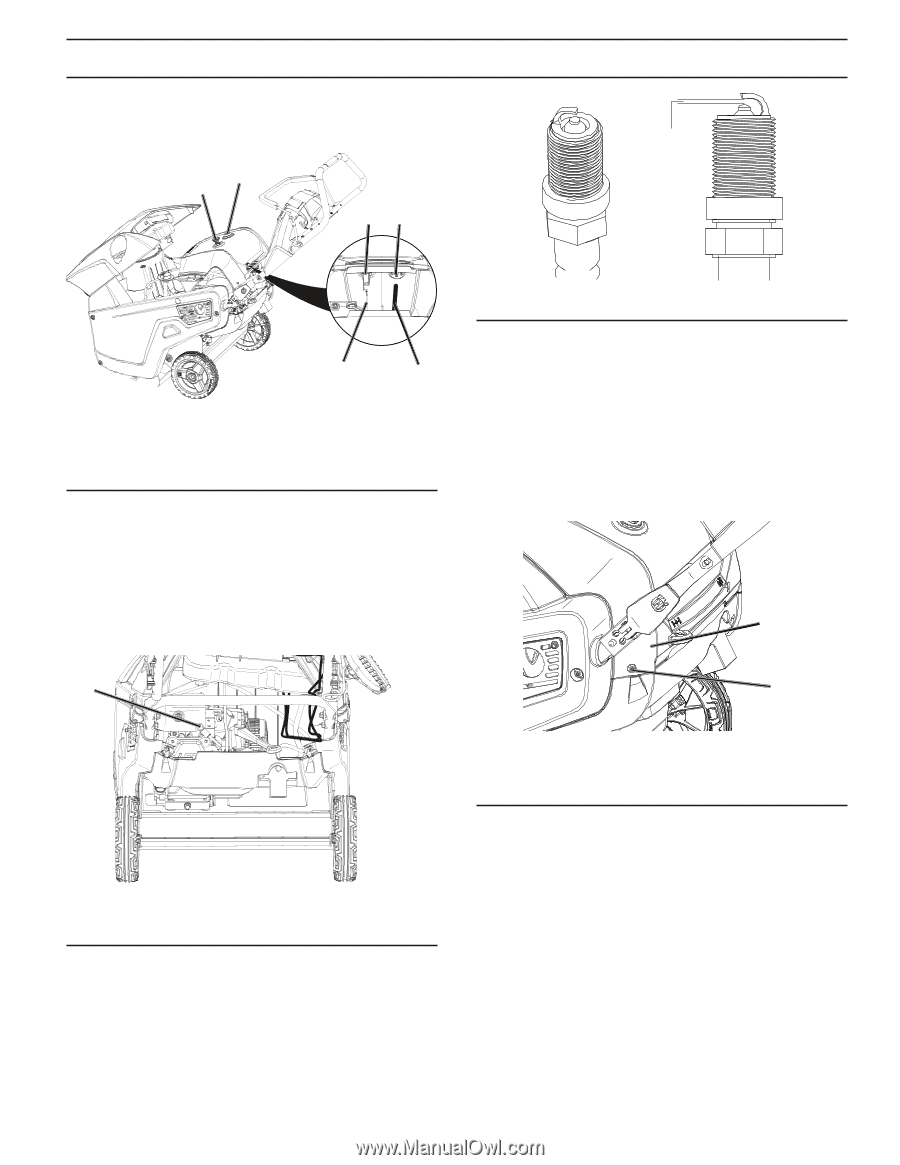
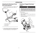
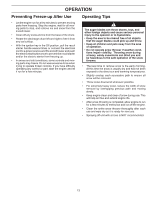
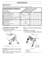
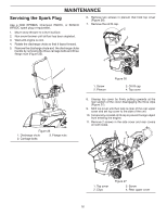
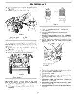
MAINTENANCE 12. Unplug electrical wires on back of ignition switch (Figure 28). 13. Pull tube off the back of the primer bulb. 4 2 24 0.030 inch (0.76 mm) Figure 30 1 3 Figure 28 1. Electrical wires 2. Ignition switch 3. Tube 4. Primer bulb 14. Lift rear upper cover and lay it to the side of the unit. IMPORTANT: The recoil rope will still be attached to the upper cover. 15. Disconnect the spark plug wire from the spark plug (Figure 29). 16. Clean around the spark plug. 17. Remove the spark plug from the cylinder head. 19. Install the spark plug and torque it to 20-22 ft-lb (27-30 N-m). 20. Connect the spark plug wire to the spark plug (Figure 29). 21. Reattach primer bulb tube to primer bulb and electrical wires on back ignition switch of rear upper cover (Figure 28). 22. Set rear upper cover in place so the two screw holes line up with the rear lower cover and side covers (Figure 31). 1 1 2 Figure 31 1. Rear upper cover 2. Screw Figure 29 1. Spark plug wire IMPORTANT: Replace a cracked, fouled, or dirty spark plug. Do not clean the electrodes because grit entering the cylinder can damage the engine. 18. Set the gap on the plug to 0.030 inch (0.76 mm) (Figure 30). 23. Reattach two screws through the rear covers and into the clip on the side cover (Figure 27). 24. Remove top oil fill cap. 25. Set top cover in place and snap three top cover clips into the rear upper cover (Figure 27). 26. Reinstall top oil fill cap. 27. Reinstall two screws in the side covers that attach to the clips on the top cover. 28. Reinstall two screws in the plenum that attach to the top cover (Figure 26). 29. Reinstall discharge chute with the hardware removed in step 5. 17
-
 1
1 -
2
-
3
-
4
-
5
-
6
-
7
-
8
-
9
-
10
-
11
-
 12
12 -
 13
13 -
 14
14 -
 15
15 -
 16
16 -
 17
17 -
 18
18 -
 19
19 -
 20
20 -
 21
21 -
 22
22 -
23
-
24
-
25
-
26
-
27
-
28
 |
 |