Husqvarna ST131 Owners Manual - Page 18
Replacing the Drive Belt
 |
View all Husqvarna ST131 manuals
Add to My Manuals
Save this manual to your list of manuals |
Page 18 highlights
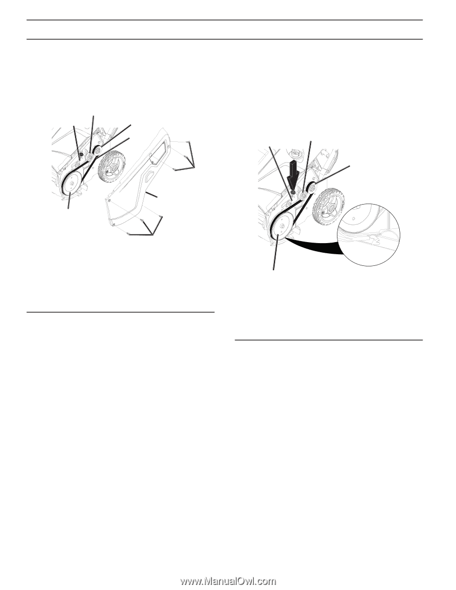
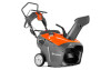
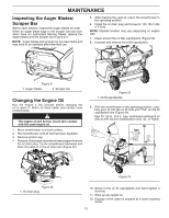
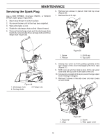
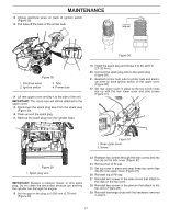
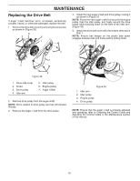
MAINTENANCE Replacing the Drive Belt If auger V-belt becomes worn, oil-soaked, excessively cracked, frayed, or otherwise damaged, replace the belt. 1. Remove the drive side cover by removing the six screws as shown in (Figure 32). 5 4 6 7 4. Install the new auger V-belt and drive pulley, routing it as shown in Figure 33. NOTE: Route the new auger v-belt first around the engine pulley, then the idler pulley, and finally around the drive pulley while pressing down on the front of the idler arm. (Figure 33). 5. Install the drive side cover with the screws removed in step 1. NOTE: Ensure belt keeper on the plastic side panel engages between belt and frame before bolting down. 1 2 3 2 1 3 2 Figure 32 1. Drive side cover 2. Screw 3. Drive pulley 4. Idler arm 5. Idler pulley 6. Engine pulley 7. Auger V-Belt 2. Remove drive pulley from the auger shaft. NOTE: Nut is welded to drive pulley and has left handed threads. 3. Remove the auger v-belt from the drive pulley. 4 Figure 33 1. Idler arm 2. Idler pulley 3. Engine pulley 4. Drive pulley NOTE: Ensure that the auger v-belt is properly adjusted and operating; refer to Checking the Control Cable and Adjusting the Control Cable in the Maintenance section of this manual. 18
-
 1
1 -
2
-
3
-
4
-
5
-
6
-
7
-
8
-
9
-
10
-
11
-
12
-
 13
13 -
 14
14 -
 15
15 -
 16
16 -
 17
17 -
 18
18 -
 19
19 -
 20
20 -
 21
21 -
 22
22 -
 23
23 -
24
-
25
-
26
-
27
-
28
 |
 |